
Written by: Choon Kiat William Chia
Platform Design – Overall
Based on the work done so far, the design of the Integrated Processing Platform (IPP) is a ten-legged fixed jacket platform supporting a 16500 tonnes topside. The topside of the IPP consists of six decks, each of 3.5 m in height to accommodate the necessary equipment and other relevant facilities. On the other hand, the majority of the jacket structure is of x-braced configurations. It is also noted that no consideration was given to the jacket joints and piles due to time constraints. Figure 1 below shows the front view of the designed IPP.
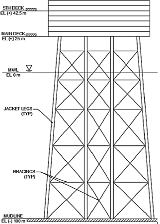
Figure 1: Front view of the IPP.
Based on the recommendation of API (2002), an additional air gap of at least 5 feet (1.5 metres) was added to the maximum 100 years return period wave. Assuming no seafloor subsidence, this results in a final airgap of 25.0 m. The team had also decided on a jacket leg spacing at the jacket top in the longitudinal direction to be 18.0 m while that for the transverse direction to be 22.0 m. Table 1 below summarises the main parameters of the IPP.
Table 1: Main parameters of the IPP.
| Parameters | Values |
| Topside Dimensions, L x W x H (m) | 70.0 x 60.0 x 21.0 |
| Airgap (m) | 25.0 |
| Operating Depth (m) | 100.0 |
| Jacket Steel Mass (tonnes) | 7290.7 |
| Assumed Topside Mass (m) | 16500.0 |
| Total Mass (tonnes) | 23790.7 |
| Jacket Centre of Gravity x, y, z (m) | 27.0, 22.0, -42.3 |
| Jacket Moment of Inertia in x-Direction, Ixx (kg m2) | 2.96E10 |
| Jacket Moment of Inertia in y-Direction, Iyy (kg m2) | 3.17E10 |
| Jacket Moment of Inertia in z-Direction, Izz (kg m2) | 1.60E10 |
General Arrangement of Topside
Figure 2 below shows the preliminary topside general arrangement for the IPP. The main, 2nd and 3rd decks are mainly for proton exchange membrane (PEM) production while the remaining decks are for storage purposes. Due to time constraints, the storage areas were predicted to the best of the ability of the team to be approximately 10800 m2. More details about the general arrangement can be found in the General Arrangement Drawing for the Topside.
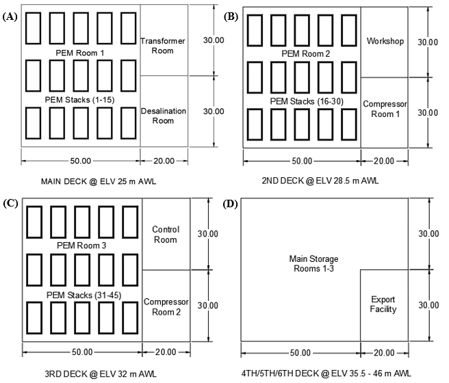
Figure 2: General arrangement for the topside (AWL denotes above mean water level).
Jacket Structural Arrangement
The jacket was designed based on the 100 year return period extreme environmental conditions as detailed in the webpage of Design Basis of the IPP. For simplicity purpose, all materials used are assumed to be API 5L Grade X70 steel. The jacket leg diameter is 2.0 m with a 40.0 mm wall thickness. According to Chakrabarti (2005), this is still acceptable as having a wall thickness greater than 0.5 inch (12.7 mm) can avoid corrosion issues while having a wall thickness smaller than 2.5 inch (50.8 mm) can avoid manufacturing difficulties as well as through thickness cracks at weld points.
On the other hand, depending on the loads that they would be subjected to, the diameters of bracings vary from 1.0 m to 1.5 m and their thicknesses vary from 15.0 mm to 35.0 mm. Generally speaking, the bigger and thicker bracings are used at the splash zone and mudline areas. Figure 3 below shows the jacket structure as modelled in DNV GL GeniE software while more details about the structural arrangement can be found in the Structural Arrangement Drawings for the Jacket. More details about the structural analysis for the jacket structure can be found in the page of Detailed Analysis for the IPP.
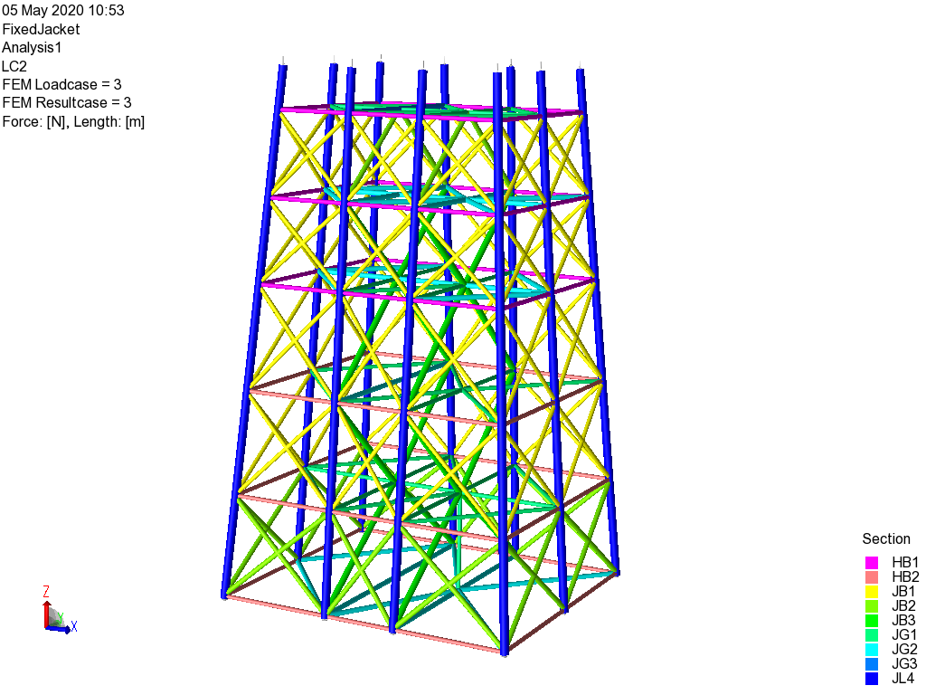
Figure 3: Jacket structure as modelled in DNV GL GeniE.
References
API. (2002). Recommended Practice for Planning, Designing and Constructing Fixed Offshore Platforms – Working Stress Design.
Chakrabarti, S. (2005). Handbook of Offshore Engineering (2-volume set): Elsevier.