Written by: Luca Grispiani
Wind Farm Layout
Wind turbines in a wind farm are spaced to maximize the amount of energy that can be generated without substantially increasing the total CAPEX (Capital expenditure), however, if the farm is significantly spread out, the inter-array cable length will increase. The spacing is, therefore, an optimization problem between compactness of the wind farm (which minimizes the CAPEX cost due to subsea cables) and the adequate separations between turbines to minimize the energy loss due to wind shadowing from upstream turbines.
Furthermore, it is important to highlight as the prevailing wind direction plays a fundamental role in the layout design of the offshore wind park. Specifically, in the appointed location, the prevailing wind blows from 210°, as it can be seen from the wind rose represented in the figure below.
.
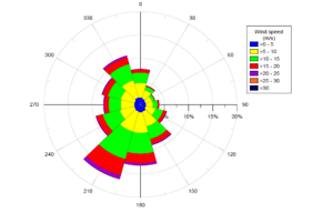
Figure: Wind Rose East 2 Marine Area (Statoil, 2014).
Therefore, in this feasibility study, it has been decided to build a wind park composed of 100 wind turbines, spaced apart 5 to 6 times the wind rotor diameter. Turbines are distributed in 10 staggered rows and 10 columns, as shown in the next figures.
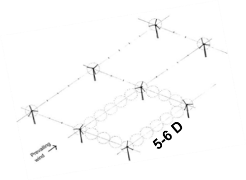
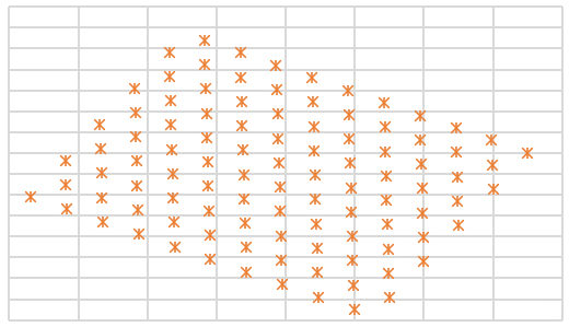
Figure: a) Wind turbines spaced apart 5-6 times rotor diameter; b) Wind Farm Layout based on prevailing wind direction.
Remarkable, the choice to deploy 100 wind turbines comes from that fact that this is a very preliminary stage of the project, so the team was looking for a simple round number in terms of Nominal Power for the whole Wind Farm (1 GW), but focusing more on the feasibility and practicability of the project. However, the East 2 Marine Area chosen in this project shows a very extensive water surface equal to 1220 km square where to install the wind farm, hence the total number of the turbines might also be increased.
Due to the large spacing of the turbines, the size wind farm would extend over a substantial area, hence there may be significant variation in the geological and subsurface conditions as well as practical restraints. Examples include sudden drop in the seafloor causing a change in water depth, paleochannels, change in ground stratification, submarine slopes, presence of foreign objects such as shipwrecks, location of important utility lines (gas pipeline, fiber optic cables), etc. A detailed site investigation program consisting of geotechnical and geophysical tests would allow establishing a 3D geological model that often contributes to the layout design stage.
Reference
Optimizing the Layout of Offshore Wind Energy Systems, J. Manwell & J. Mcgowan. 2008, Marine Technology Society Journal 42(2):19-27, DOI: 10.4031/002533208786829188
Integrated Layout and Support structure Optimization for Offshore Wind Farm Design, T. Ashuri, C. Ponnurangam, J. Zhang and M. Rotea, (Septmber 2016), Journal of Physics: Conference Series, Volume 753.
Wind Energy Engineering, Trevor M. Letcher, 2017, Elsevier, ISBN: 978-0-12-809451-8
Offshore Wind Farms, Technologies, Design and Operation, Edited by Chong Ng and Li Ran, elvisier, Amsterdam, ISBN: 978-0-08-100780-8