Written by: Andre Santos
- Transportation System Hydrogen
- Hydrogen Storage System OFFSHORE STORAGE SYSTEM REPORTOFFSHORE STORAGE SYSTEM REPORTPtt Storage System Hydrogen pptx
This describe a storage system where the hydrogen is kept inside the tank
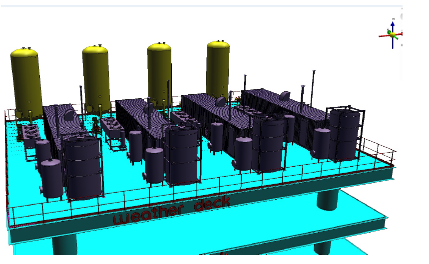
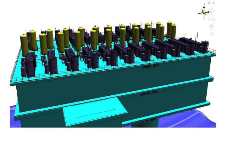
1.1 Offshore storage system.
1.1 Offshore storage system.
Produced hydrogen gas can be compressed at 700 bars by an ionic compressor to reduce storage volume. However, this pressure of gas can be increased gradually in five steps where the energy is likely to continue losing and close to zero. Therefore, this process requires a minimal maintenance requirement where the compressors seems to be suitable for offshore operation. First, this quantity which is being produced about 377400 kg is likely to related to the density of hydrogen at elevated pressure which can be estimated by using thermodynamics principles. This theory is associated with van der Waals equation , where, P, V and T are represented the pressure, volume and temperature of the gas respectively; moreover, n represents the number of moles of gas present, and R is the universal gas constant (8.314 N. m/mol. K). Furthermore, the equation which is likely to be used two constants (α and b) are likely to be
determined by experiment process for hydrogen where the values of 0.0244 Pa. (m3 ) 2.mole -2 and 0.0266*10-3 m3.mole -1 for α and b respectively .However , the compressibility factor is likely to be introduced as variable, Z which represents the deviation of a real gas from the ideal gas approach by a given equation : PV=nZRT where the behavior of hydrogen can be deviated such a significant way from the ideal gas model. However, the quantity of Hydrogen in storage system can be estimated by its compressed volume which is 9430.05 NM3 normal volume cubic meter. Moreover, it can be calculated 39.76 kg/m3 *9430.05 m3 as where the value 39.76 kg/m3 is the density of hydrogen by compressibility z factor 1.4 at 70 Mpa or 700 bar pressure. Therefore, the result is likely to be 374938. 788 kg which nearly compared to 374440 kg the produced quantity of Hydrogen.
Fig 1 . Compressibility factors of hydrogen at High pressure.
|
Pressure (MPa) |
0.1013 |
5 |
10 |
20 |
30 |
35 |
40 |
50 |
70 |
100 |
|
Z |
1 |
1.032 |
1.065 |
1.132 |
1.201 |
1.236 |
1.272 |
1.344 |
1.489 |
1.702 |
Table 1 – Hydrogen compressibility factors (Z) at 20°C Pressure (MPa)
|
HHV (MJ/M3 |
LHV(MJ/M3) |
Normal conditions |
|
12.75 |
10.8 |
At 15 |
|
12.71 |
10.8 |
At normal conditions |
|
11.7 |
9.9 |
At 25 |
|
5.312E+7 |
4.491E+7 |
374400 Kilograms |
Table 2 – Volumetric energy density of hydrogen.
H2(g) + ½O2(g) ↔ H2O(g) ∆Η298.15 Κ = −241.826 kJ/mole this equation has been considered applicable when hydrogen is likely to be produced as vapor or gas. In , addition , we considered at normal 20 which is nearly associated with conversion factor LVH lower Heating value 119.96 and High Heating value which is 141.88.Therefore, LVH is likely to be considered because of gaseous state where 119.96 *37400 converted to Mj 4.491E+7 MJ.
1.2 Storage System Hydrogen Technology.
The group has been considered the high pressure of hydrogen at gaseous state and the offshore environment related to project involved including the similarities with oil and gas industry. Furthermore, hydrogen gas has been considered by its rapidly refueling at this state. However, three main point were considered to design a capable tank to store hydrogen compressed gas .
- Material
- Thickness
- Capacity
1.3 Design Pressure vessel for storage System
|
Code ASME Design Material SA 516 Grade 70 Code design |
|
Grade |
Tensile Strength Ksi [MPa] |
|
55 |
55-75 |
|
60 |
60-80 |
|
65 |
65-85 |
|
70 |
70-90 |
Tab 3 Mechanical properties of A516 shows that at grade 70 the material is likely to have the durability.
|
Month |
Carbon Steel Price |
Carbon Steel Index |
Stainless steel 304 Price |
Stainless Steel 304 INDEX |
|
Oct-19 |
621 |
155.6 |
2622 |
139.7 |
|
Sep-19 |
645 |
161.7 |
2547 |
135.7 |
|
Aug-19 |
657 |
165.3 |
2406 |
128.2 |
|
Jul-19 |
660 |
167.4 |
2381 |
128.2 |
Tab .4 this shows the low cost of carbon comparing to other material .
|
Carbon content |
Manganese content |
Ductility |
|
|
High carbon |
0.6-1.25 wt. % |
0.3-0.9 wt. % |
Low |
|
Medium carbon |
0.25-0.60 wt.% |
0.60-1.65 wt.% |
low |
|
Low carbon |
0.25 wt. % |
NA cold work |
High ductility |
Tab. 5
Although , low carbon has been described as soft and low strength , they have the highest ductility which make them available for welding and low cost .However, an exception of low alloy steel which is likely considered low carbon has a high strength and contain others metals such as copper, vanadium , nickel and molybdenum. According to Matmatch, once they are combined their content
|
Type |
AISI/ASTM name |
Carbon content (wt.%) |
Tensile strength (MPa) |
Yield strength (MPa) |
Ductility (% elongation in 50 mm) |
Applications |
|
Low |
1010 |
0.10 |
325 |
180 |
28 |
Automobile panels, nails, wire |
|
Low |
1020 |
0.20 |
380 |
205 |
25 |
Pipes, structural steel, sheet steel |
|
Low |
A36 |
0.29 |
400 |
220 |
23 |
Structural |
|
Low |
A516 grade A |
0.31 |
485 |
260 |
21 |
Low-temperature pressure vessels |
|
Medium |
1030 |
0.27 – 0.34 |
460 |
325 |
12 |
Machinery parts, gears, shifts, axles, bolts |
|
Medium |
1040 |
0.37 – 0.44 |
620 |
415 |
25 |
Crankshafts, couplings, cold headed parts. |
|
High |
1080 |
0.75 –0.88 |
924 |
440 |
12 |
Music wire |
|
High |
1095 |
0.90 – 1.04 |
665 |
380 |
10 |
Springs, cutting tools |
is likely to be 10 wt. %. This means that it retains ductility and high strength and it can be claimed
that they are resistant to corrosion easily. However, at temperatures below 120°C carbon steel can be used up to high pressures. At elevated temperatures and significant pressures hydrogen will penetrate carbon steel and react with the carbon to form methane. This results in a loss of ductility and cracking or blistering of the steel. For high temperature applications steel alloys containing molybdenum and steel are satisfactory. However, low carbon has been chosen to be the level of type of material of the tank formable and machinable. In addition, ASTM is considered structurally appropriate steel for pressure vessel. Therefore, this toughness is likely to associated with manufacturing vessels for pressurised gas (LPG, butane and propane tanks), parts for steam boilers, pressure piping and compressors etc.
|
Grade |
Maximum C % for thickness t (mm) |
Mn % for thickness t (mm) |
Si % |
P % max |
S % max |
||||
|
6-12.5mm |
12.5-25mm |
25-50mm |
>50mm |
≤12.5mm |
>12.5mm |
||||
|
A516 Grade 55 |
0.18 |
0.2 |
0.22 |
0.25 |
0.55-0.98 |
0.60-1.30 |
0.13-0.45 |
0.035 |
0.035 |
|
A516 Grade 60 |
0.21 |
0.23 |
0.23 |
0.25 |
0.6-0.9 |
0.80-1.20 |
0.13-0.45 |
0.035 |
0.035 |
|
A516 Grade 65 |
0.24 |
0.26 |
0.26 |
0.28 |
0.85-1.20 |
0.85-1.20 |
0.13-0.45 |
0.035 |
0.035 |
|
A516 Grade 70 |
0.27 |
0.28 |
0.28 |
0.3 |
0.85-1.20 |
0.85-1.20 |
0.13-0.45 |
0.035 |
0.035 |
Tab 7 shows the ASTM A516 material Chemical Composition.
|
Grade |
Tensile strength |
Minimum yield strength |
Minimum elongation (%) gauge length |
|
|
(MPa) |
(MPa) |
50mm |
200mm |
|
|
A516 Grade 55 |
380-515 |
205 |
27 |
23 |
|
A516 Grade 60 |
415 – 550 |
220 |
25 |
21 |
|
A516 Grade 65 |
450 – 585 |
240 |
23 |
19 |
|
A516 Grade 70 |
485 – 620 |
260 |
21 |
17 |
Tab 8 SA516 material Mechanical Property: shows that A516 is considerably for high resistance, good weldability and suitable for boiler fabrication including low temperature.
Therefore, the default allowable stress is likely to be 15150 psia, according to the ASME code allowable for carbon steel.
1.4 Geometry and layout (PRESSURE VESSEL)
Geometry of pressure has been associated with different factors such as maximum allowance, stress, design pressure, corrosion, density of material, price and thickness. The group has decided to use 700 bar as the design pressure which related to the type of the tank is associated with type IV.
- The following 4 types of high-pressure vessels are classified
- Type I: pressure vessel made of metal
- Type II: pressure vessel made of a thick metallic liner hoop wrapped with a fiber-resin composite.
- Type III: pressure vessel made of a metallic liner fully wrapped with a fiber-resin composite.
- Type IV: pressure vessel made of polymeric liner fully wrapped with a fiber-resin composite. The port is metallic and integrated in the structure (boss).
Therefore, the tank is considered geometrically cylinder due to less cost and easy circulation of the hydrogen inside the tank comparing to Spherical vessel.
Pressure vessel cylindrical shell.
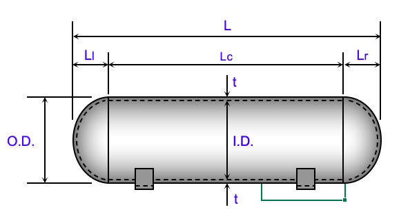
This figure demonstrates the geometry of pressure vessel in storage system.
where {\displaystyle \sigma _{\theta }} is representing hoop stress, or stress in the circumferential direction = , {\displaystyle \sigma _{long}} is stress represented in the longitudinal direction σlong = p(r-0.4t)/2tE, p is internal gauge pressure, r is the inner radius of the sphere, and t is thickness of the sphere wall. However, it is likely to be into consideration the winding angle of 54.7-degree carbon fibers vessels which may give twice the strength of both longitudinal and circumferential stress.
2.1 Calculation of the pressure vessel.
Allowable stress can be calculated by yield strength 260 Mpa of the material calculated to the safety factor of material 3 .5 as the safety factor is likely to be described as how much is strong the intended loads .Therefore , Allowable stress = this is likely to define the lifecycle of the tank .Thickness min required t = where E is the joint efficiency which is related to the thickness , weight of the tank , P is likely to be the external pressure or design 700 bar .
|
Ratio 1:4 |
M(meter) |
DESIGN PRESSURE |
10152.6 |
bar |
|
DIAMETER |
1 |
ALLOWABLE STRESS (s) |
23300 |
Psi |
|
Radius |
0.5 |
External radius |
19.68 |
inch |
|
LENTGH |
4 |
Max Allowance Pressure |
558.49 |
psi |
|
Min. THICKNESS |
0.09 |
Wall thickness |
1.7 |
inch |
|
Corrosion Allowance |
0.125 |
2.2 SIZING HORIZONTAL VESSEL
Tab 9
Lc = length longitudinal cross, Lr – length right, LI- length left L = Ll+Lc+Lr =
O.D – outside diameter, ID- inside diameter, OD=ID+2*t/12 = 1.2 m
total cross area is likely to be where
vapor space as a cross-sectional L = Ll+Lc+Lr = 4.4 m
t = ; t = = 3.9 inch converted to meter is 0.09 M. In addition, has been assumed 23300 psi as allowable stress in division 3 tank type 4 according to design code ASME.
However, P = , seems to be considered max allowance pressure which is likely to be defined as workable pressure. This pressure is used as a relief device to maintain the tank safe when it is shutdown or alarm. Furthermore, wall thickness t = + CA = 1.7 inch which is equivalent 0.04318 Meter ; where CA represent the corrosion allowance which is likely to be considered a crucial point at tank process where 0.125 has been chosen as a value of corrosion allowance to prevent corrosion and failure. Moreover, R is considered the internal diameter.
2.3 LOAD OF THE TANK
|
A(leftend)=(*(2*(OD/2) ^2+Ll^2/e*LN((1+e) /(1-e))))/2 |
1.46 |
m |
|
|
|
A(cylinder) = *OD*Lc 15.119 |
m |
|
|
|
|
A(rightend)= (*(2*(OD/2) ^2+Lr^2/e*LN((1+e)/(1-e))))/2 |
1.46 |
m |
|
|
|
A(total) = A(left end)+A(cylinder)+A(right end) 18.051 m |
|
|||
|
where: e = and Le = Ll or Lr |
||||
|
Surface Area |
|
|
|
|
Tab. 10
|
2609.3 |
Ibs |
1183.5 |
Kg |
|
||||
|
26907.9 |
Ibs |
12205.2 |
Kg |
We(cylinder)= A(cylinder)*((t/12) *ws+wi*ti/1 |
||||
|
2609.3 |
Ibs |
1183.5 |
Kg |
|
||||
|
1000.0 |
Ibs |
453.592 |
Kg |
Wt. This has been considered as an input value |
||||
|
33126.5 |
Ibs |
15025.9 |
Kg |
|
EMPTY WEIGHT OF THE TANK
Tab.11
Therefore, the total value of empty tank is converted to ton which is 16.5 ton.
Tab.12 shows the volume of tank which is likely to be filled by Hydrogen.
|
V(left end) = |
2.74 |
ft.^3 |
V (left end) = (4/3*pi*(ID/2)^2*(Ll-t/12))/2 |
|
|
V(cylinder) = |
110.94 |
ft.^3 |
V(cylinder) = pi*ID^2/4*Lc |
|
|
V(right end) = |
2.74 |
ft.^3 |
V(right end) = (4/3*pi*(ID/2)^2*(Lr-t/12))/2 |
|
|
V(total) = |
116.43 |
ft.^3 |
V(total) = V (left end) +V(cylinder)+V(right end) |
|
|
TOTAL |
870.97 |
gal. |
V(total) = (V(left end)+V(cylinder)+V(right end))*7.4805 |
|
Therefore, the total volume is likely to be converted to m3 which is defined as 24.6631=24600 Litter (L).In addition , it was consider 24.663*39.76kg/ to define the quantity of Hydrogen in 1 tank . Therefore, 980.60kg of hydrogen is likely to be the value of the capacity of the tank.
Weight of full tank.
|
Wc(left end) = |
171.3 |
lbs. |
Wc(left end) = V(left end)*(t/12)*wc |
|
Wc(cylinder) = |
6926.3 |
lbs. |
Wc(cylinder) = V(cylinder)*wc |
|
Wc(right end) = |
171.3 |
lbs. |
Wc(right end) = V(right end)*wc |
|
Wc(total) = |
7268.9 |
lbs. |
Wc(total) = Wc(left end)+Wc(cylinder)+Wc(right end) |
Tab. 13 shows the weight of the tank when is filled by Hydrogen.
Therefore, the group has considered the total weight of tank + full content. This means that empty weight +full weight tank where Total =We+Wc = 33126.5 + 7268.9 = 40395.4 Ibs the value is likely to converted by kg and ton which are 18323.4 kg and 20.1 ton. In conclusion, the numbers of the tank have been calculated by the quantity of hydrogen produced and quantity of hydrogen
in 1 tank 374400 kg /980.60kg = 381.80 which is likely to be 382 tanks on the offshore platform.
REFERENCES
- Pressure vessel calculations weights excel.
- Eugene F. Megyese Tulsa Oklahoma pressure vessel inc.1973
- Ahmed Ibrahim*, Yeong Ryu, Mir Saidpour, 2015.
- E. Tzimas et al, 2003.
- Daniel A. Crowl and Scott Tipler, American institute of chemical engineers, 2013
- International Journal of Emerging Engineering Research and Technology Volume 2, Issue 3, June 2014, PP 1-8 ISSN 2349-4395 (Print) & ISSN 2349-4409 (Online).
- Yu Wang et al. / Energy Procedia 29 (2012) 657 – 667.
- IRENA, 2019b. Navigating the way to a renewable-powered future: Solutions to decarbonise shipping. International Renewable Energy Agency, Abu Dhabi.
- ASME pressure vessels & water storage Tanks Highland Tank.
- Sofoklis S. Makridis1,2 ,2016.
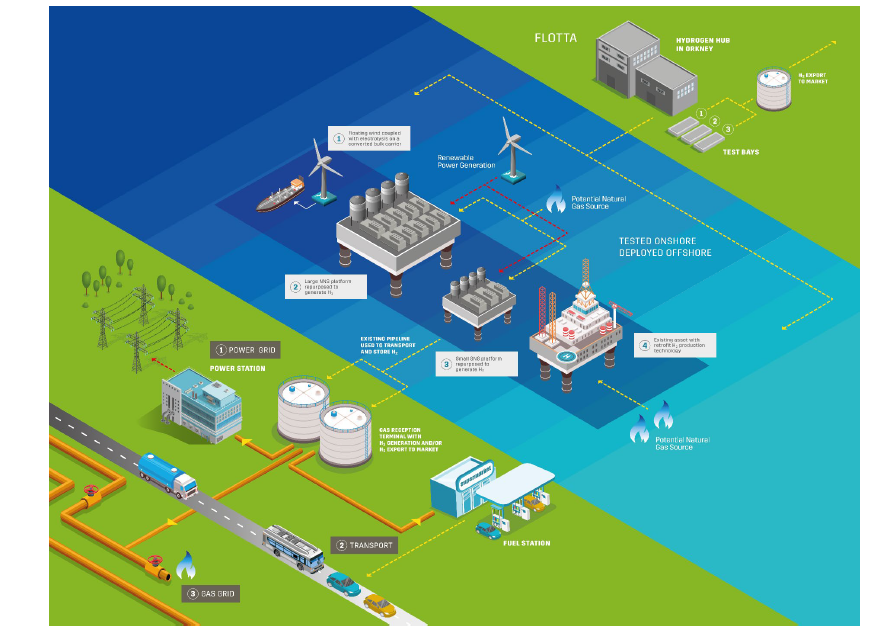
- TRANSPORTATION SYSTEM Hydrogen can be transported and stored gradually by 4 main methods: ■ Liquid (cryogenic) hydrogen ■ Ammonia ■ Hydrogenated liquid organic hydrogen carrier ■ Compressed gaseous hydrogen.However, it seems to be crucial the process of hydrogenation and dehydrogenation where the lowest cost is dependably on states a reason why gaseous is considered costly effective. Hydrogen has been compressed at 9430.50 Nand stored in tank at high pressure nearly 700 bar at gaseous state. However, the low volumetric density of hydrogen can be considered an issue to storage and transportation; moreover, the distance due to offshore environment. However, hydrogen can be transported by truck, ships and pipelines. Therefore, pipelines have been chosen as the most suitable option due to similarity operation with natural gas and geological site.1.1 Technological option for Transportation system.Transportation System HydrogenNorth Sea has been chosen as geological location for hydrogen production, storage and transportation. However, hydrogen is likely to be transported by pipelines at low pressure as reported by Pilar Blanco-Fernandez, 2017 it is more safe to transport hydrogen at low pressure.
Site Water depth Distance to shore Quantity North Sea, Peterhead 100 m 50 km 374400 kg Tab 1 shows the details of the operational field.
Fig 1. shows the Pipelines system at Peterhead.
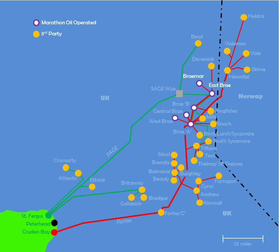
Brae’s platforms, pipelines and infrastructure are also used by third parties> Source: Marathon Oil. 
https://www.thinkdefence.co.uk/2015/05/north-sea-infrastructure-defence-applications/gas-ops/ 1.2 Pipelines transmission system.
Pipeline transport for compressed gaseous hydrogen is likely to considered in general the most cost-effective approach of transporting large volumes of it by long distances. Furthermore, the transportation can be operated in pure form or be blended into natural gas above the limits or restrictions prescribed by policies regulations or contract regulations. However, certain factors should be considered in pipelines transportation.
- Velocity – this is where the volume flow rate associated with pressure and temperature is likely to be divided by section area.
- Gas pressure – the operation pressure inside the pipe.
1.3 Brittle fracture and environmental damage mechanisms.
Two main point has been considered: For internal corrosion.
- Hydrogen Gas Embrittlement (HGE) at ambient temperature
For external corrosion.
- Stress Corrosion Cracking (SCC) of line pipe materials in underground environments.
REFERENCE
- https://www.itmpower.com/images/NewsAndMedia/Reports/New_energy_value_chains_Hydrogen_as_an_energy_carrier_DNV-GL November_20.
- https://assets.publishing.service.gov.uk/government/uploads/system/uploads/attachment_data/file/866379/Phase_1_-_OGTC_-_Hydrogen_Offshore_Production.
- American Petroleum Institute, “Specification for Line Pipe, API Specification 5L,” American Petroleum Institute, 41st Edition, April 1, 1995.
Ptt Storage System Hydrogen pptx