
Written by: Raul Rogerio Pimentel Ribeiro
A literature review has been carried to define the possible options for hydrogen production to attend the characteristics of the project and the energy profile as described in the offshore wind farm section. Regardless of the technology applied, the reaction is endothermic and requires energy to perform the process. The reaction and energy required are:
anode: 2H20(l) → O2(g) + 4H+ (aq) + 4e- E0 = +1.229 V
cathode: 2H+(aq) + 2e- → H2(g) E0 = 0 V
cell: 2H2O → 2H2 (g) + O2 (g) E0 = -1.229 V
ΔH =ΔG + TΔS
Where (J/mol) is the variation of enthalpy, (J/mol) is called as Gibbs free energy and corresponds to the minimum electrical energy required, and (J.K/mol) corresponds to the minimum thermal energy required to the process where T is the process temperature and the entropy variation (Meier, K., 2014). This equation suggests that the thermal energy demand can be compensated by the electrical energy and the temperature settle can also interfere in electrical energy demand. Based on the enthalpy variation, the required cell voltage (Vc) is defined as:
Vc =ΔH/2F
Where F is the constant of Faraday (96,485.3365 C/mol) and the number 2 is related to the number of electrons of hydrogen molecule(Meier, K., 2014). The higher heating value (HHV) often represents the change of enthalpy, thus, the required cell voltages for each heating value are:
Vc (HHV) = (141.86 x M) / 2F
Vc (LHV) = (119.93 x M) / 2F
Where corresponds to the molar mass of hydrogen (2.015 g/mol). As exposed in the above equations, the temperature performs an important role in energy demand in order to produce hydrogen(Meier, K., 2014). The quantity of hydrogen (mH2) production is dependent on available energy (P) and the efficiency of the electrolyser (η). modeled by:
mH2(kg)= (P x M x η) / (Vc x 2F)
The final efficiency of the system can be calculated by the ratio between the specific energy demand to produce 1 kg of hydrogen and the thermodynamic minimum energy required as defined by the higher heating value voltage cell which is 39.405 kWh/kg (Meier, K., 2014).
The final result brings three main Electrolyser concepts to be considered in this project.
- Concept 1: Alkaline Electrolyser (AEL)
- Concept 2: Proton Exchange Membrane (PEM)
- Concept 3: Solid Oxide Electrolyser Cell (SOEC)
In order to evaluate the applicability of each concept and ranking then, the decision matrix has been generated taking into account the factors described in table 2. Each factor has a relative score from a range of one (worst) to three (best) in order to rank the referred concept. Based on the relative weighting of each factor and the score, the highest final score (sum of all scores) will define the adopted concept for hydrogen production. Suitability is referred to as the capacity of adaptation of energy fluctuation once it is a crucial characteristic of wind farm output. The load capacity would mean the capacity of operation by applying a percentage of the nominal.
Table 2: Considered factors to define Electrolyser Technology and their relative weighting
| Factors | Relative Weighting |
| Efficiency | 20% |
| Life Cicle | 10% |
| Required Area | 25% |
| Cost | 10% |
| Suitability | 15% |
| Technology Maturity | 20% |
Concept 1: Alkaline Electrolyser (AEL)
Alkaline Electrolysers are the most applied solution for hydrogen obtention regarded to its maturity as technology. The cells of Alkaline Electrolysers are conventionally designed with electrodes that are assembled perforated metals and surfaces containing porous which are directed to the diaphragm. The connections are made in series and it is left a gap from the plates and the diaphragm. The configuration described above performs a considerable distance between cathode and anode whose losses increase mainly from Ohmic losses (heat) and allows the creation of bubble overpotential (Smolinka, T., et al., 2015). According to Smolinka, T. et al. (2015), the conventional AEL cell is basically composed by an anode compartment (1), cathode compartment (2), diaphragm (3), electrodes (4), cell frame (5), DC power supply (6), end plates (7), and a gas-water separator (8) as shown in Figure 2.
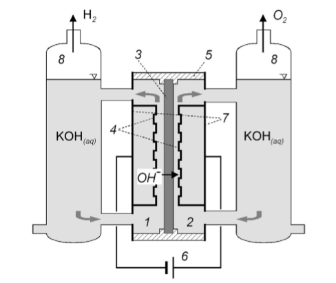
Figure 2: Simplified schematic diagram of a conventional AEL cell (Smolinka, T., et al., 2015).
The performance of this device depends on the materials utilised. The state of the art of this technology suggests different combinations of elements (transition metals and oxides) for cathodes and anodes terminals in order to provide better performance such as Pt2Mo, Hf2Fe, and TiPt for cathodes and RuO2 for anode (Smolinka, T., et al., 2015).
The purity of the hydrogen produced is around 99.3% to 99.8% without any additional p method. However, the fluctuation of power source may generate part load output which decreases gas purity. Thus, the Alkaline Electrolysers are limited in 20% of the part-load in order to avoid losses on gas purity (David, M., et al., 2019).
In order to follow the commercial standard of hydrogen purity, the implementation of systems of gas purification to Alkaline Electrolyser Plants which is generally achieved after a two-stage purification process and the hydrogen drying system is required for the final product that accounts to a loss of up to 8% (Smolinka, T., et al., 2015). On the other hand, the efficiency of AEL is around 54 – 73% based on the power demand to produce hydrogen (David, M., et al., 2019). These values may vary among different devices and companies, however, the consumption per normal-meter cubic (Nm3) is around 6 kWh. Also, there is a relation between power consumption and the size of the facility. It tends to improve in efficiency as the size of the equipment increases. The AEL system is flexible in operation means and it can be utilised on systems varying between 5 kW to 3.2 MW (Ohta, T., 2009). For hydrogen production capability, it is estimated that for per MW of alkaline electrolysers installed, approximately 100 m2 of space is required. Table 3 summarises the considered factors for electrolyser technology.
Table 3: Considered factors for AEL Technology
| Factors | Response |
| Efficiency | 54-73% |
| Life Cycle | 20 years |
| Required Area | 100 m² per 1 MW |
| Cost | Low cost |
| Suitability | from 20-30% nominal capacity |
| Technology Maturity | Commercialized |
Concept 2: Proton Exchange Electrolyser (PEM)
Proton Exchange Membrane (PEM) for water electrolysis is another commercialised alternative for performing hydrogen production on a large scale due to its operational versatility. PEM water electrolysers are able to operate under high current density and capture energy even during large power fluctuation without lacking efficiency rate (Carmo, M., et al., 2013). These characteristics allow PEM EL to suit into dynamic systems such as wind power production once the power delivered performs a high level of fluctuation followed by intermittent periods. The design of PEM EL is shown in Figure 3. The cell is divided by five main parts: the membrane which is a solid polymer, current distributor, bipolar plate (BiP), and the Electrode (Electrocatalysts) that is responsible for creating the propitious environment for water splitting process with increased reaction area for the transport of protons and electrons (Smolinka, T., et al., 2015). The water comes from the bottom of the device and, in contact with the electrocatalysts and membrane, disassociates the hydrogen and oxygen from its previous form. However, the relation between hydrogen production rate and membrane thickness is not trivial, the optimum point must be evaluated case by case. In most of the cases, the purity of the hydrogen produced is 99.999% and it revokes the necessity of purification systems (Carmo, M., et al., 2013).
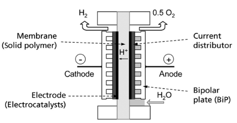
Figure 3: Principle design of a PEM EL cell (Smolinka, T., et al., 2015).
Nowadays, the quantity of platinum on cathode catalysts has decreased without affecting considerably the efficiency and durability and reducing the cost of the equipment. The quantity of this noble material lowered in more than 50% going from 1 mg per cm2 to less than 0.5 mg per cm2 (Carmo, M., et al., 2013). The system efficiency is another point where Proton Exchange Membrane Electrolysers are highlighted. The efficiency may achieve 86% based on temperature and pressure conditions during large production rates (Smolinka, T., et al., 2015). This higher energy efficiency may be explained by, among other reasons, the low Ohmic losses and, when considered the integrated system in order to define the energy efficiency of PEM hydrogen production, this difference increases significantly due to the necessity of compression once PEM EL systems do not require further compression addition for lower pressures (up to 30 bar) (Felgenhauer, M., and Hamacher, T., 2015).
Figure 5 shows a schematic that describes the operation of a typical pressure-balanced PEM Electrolyser system. In summary, the energy supply provides power to the PEM electrolysis stack in DC current, the water is pumped into the anode side. After passing by the PEM EL stack, the hydrogen achieves the gas/water separator, further, the hydrogen passing through the condensate trap, deoxidiser, and finally, dryer in the output of the hydrogen plant. The water from the separator is pumped back to the system in order to achieve zero waste. As mentioned before, the system does not require compressor input. This system will be related to the type of chosen storage system. This system has the characteristics of being compact as one more positive component in favor of this technology. It is required around 20 m2 per megawatt installed for PEM electrolysers (Hydrogenics, n.d.; Jepma, Kok, Renz, Schot, & Wouters, 2018). Table 4 summarises the considered factors for PEM technology.
Table 4: Considered factors for PEM Technology
| Factors | Response |
| Efficiency | 67-86% |
| Life Cycle | 15 years |
| Required Area | 20m² per 1 MW |
| Cost | High installation cost |
| Suitability | From 1-10% nominal capacity |
| Technology Maturity | Commercialized |
Concept 3: Solid Oxide Electrolyser Cell (SOEC)
SOEC technology is promising regarded in producing hydrogen. The expected efficiency of this technology is comparable to PEM electrolysers (Chi, J., & Yu, H., 2018) and SOEC can potentially achieve efficiency up to 100% based on the development of the technology. Nowadays, the maturity of the concept is regarded as in the research and development phase (Chi, J., & Yu, H., 2018). This characteristic is crucial and also a cutting edge to choose between possible suitable technologies. The SOEC technology is still on a laboratory/demonstration scale which makes the technology unfeasible. Based on this fact, the dimensions for large scales are not established but it is expected that this system becomes compact. The suitability of the system is still a challenge once the laboratory response has shown limitation regarded to stability and energy fluctuation. On the other hand, the cost is expected to be the highest cost-benefit over established technologies.
Table 5: Considered factors for SOEC Technology
| Factors | Response |
|---|---|
| Efficiency | 72-88% |
| Life Cycle | 20 years (potentially) |
| Required Area | Compact (expected) |
| Cost | Potential Low Cost |
| Suitability | Unstable |
| Technology Maturity | Research & Development |
Decision Matrix for Electrolyser System
After evaluating three different concepts, the decision matrix can be generated. It is worth mentioning that the decision matrix has been designed allows by following a flowchart that provides a better understanding of the hierarchy of factors and the pathway through making a decision The flowchart is shown in figure 4.
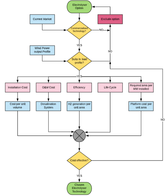
Figure 4: Flow chart of the criteria to define Electrolyser technology applied.
The factors considered while choosing the Electrolyser concept and their relative weightings are exposed in Table 1. Based on that, it is possible to show the decision matrix that was developed to define the electrolyser technology of this project and it can be seen in Table 6.
Table 6: Decision Matrix for defining the most suitable Electrolysis Technology
The PEM option has been chosen as the most suitable option based on its efficiency, the required area, suitability regarded to the input energy profile, and technology maturity. Those topics were described on the concept sub-topic.
REFERENCES
Carmo, M; Fritz D; Mergel J; Stolten D (2013). “A comprehensive review on PEM water electrolysis”. International Journal of Hydrogen Energy. 38 (12): 4901-4934. doi: 10.1016/j.ijhydene.2013.01.151.
David, M., Ocampo-Martínez, C., & Sánchez-Peña, R. (2019). Advances in alkaline water electrolyzers: A review. Journal of Energy Storage, 23, 392–403. doi: 10.1016/j.est.2019.03.001
Flowers, P., Theopold, K., Langley, R., & Robinson, PhD, W. R. (2019). Chemistry 2e. Houston, Texas: OpenStax. Retrieved from : https://openstax.org/books/chemistry-2e/pages/1-introductionhttps://openstax.org/books/chemistry-2e/pages/1-introduction
Meier, K. (2014). Hydrogen production with sea water electrolysis using Norwegian offshore wind energy potentials Techno-economic assessment for an offshore-based hydrogen production approach with state-of-the-art technology. Int J Energy Environ Eng , 5(104), 1–12. doi: DOI 10.1007/s40095-014-0104-6
Felgenhauer, T. Hamacher, State-of-the-art of commercial electrolyzers and onsite hydrogen generation for logistic vehicles in South Carolina, Int. J. Hydrogen Energy 40 (2015) 2084–2090.
Ohta, T. (2009). Energy carriers and conversion systems. Oxford, U.K.: Eolss Publishers.
Rekioua, D. (2020). Hybrid Renewable Energy Systems: Optimization and Power Management Control. Cham, Switzerland: Springer.
Sarrias-Mena, R., Fernández-Ramírez, L. M., García-Vázquez, C. A., & Jurado, F. (2015). Electrolyzer models for hydrogen production from wind energy systems. International Journal of Hydrogen Energy, 40(7), 2927–2938. doi: 10.1016/j.ijhydene.2014.12.125
Smolinka, T., Ojong, E. T., & Garche, J. (2015). Hydrogen Production from Renewable Energies—Electrolyzer Technologies. Electrochemical Energy Storage for Renewable Sources and Grid Balancing, 103–128. doi: 10.1016/b978-0-444-62616-5.00008-5