


Thermodynamic Cycle
Carbon dioxide is a natural refrigerant which involves high working pressures. The supercritical portion of the carbon dioxide cycle which is also known as the transcritical cycle, reaches above 1067psia. The phase diagram of CO2 is shown in figure 1 showing critical point at a temperature of 88o F.
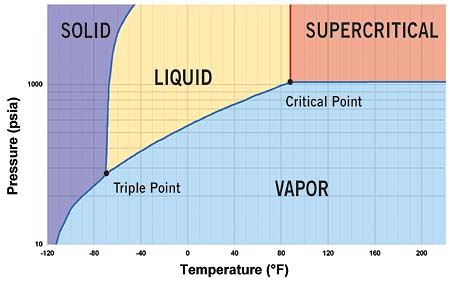
Fig 1: Phase diagram of CO2 with critical point at 88o F and 1067psia.
In the subcritical cycle, using conventional refrigerants e.g. R134a, all the processes (Evaporation, compression, Condensation, Expansion) on ph diagram occur below the critical point. However, it is a bit different in the case of the transcritical cycle using R744 (CO2) as a refrigerant. Although the process looks the same the heat rejection process occurs above the critical point. There is no condensation process in the transcritical cycle and temperature decreases through all of the heat rejection process where as the temperature stays constant during the heat rejection process in the subcritical cycle. The heat rejection process in transcritical cycle is called Gas Cooling. The pressure-enthalpy diagrams of subcritical and transcritical cycles are shown in figure 2 and figure 3 (Staub et Al., 2004)
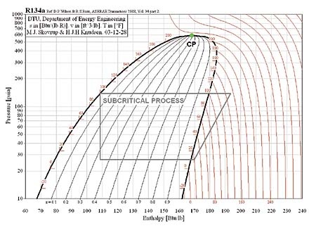
Figure 2: Subcritical cycle (R134-a conventional Refrigerant
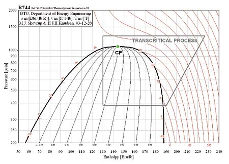
Figure 3: Transcritical cycle (R744, Natural Refrigerant
The theoretical reference cycle for heat pumps, where heat is rejected and absorbed at constant temperature and constant pressure, is known as the reversed Carnot cycle. But in the case of the transcritical cycle, where heat is absorbed at constant temperature and subcritical pressure and the heat is rejected at gliding temperature and supercritical pressure, the theoretical reference cycle is the modified Lorentz cycle. The Ideal Lorentzen cycle is the reference for the ideal cycle for CO2 heat pumps while the real cycle for CO2 heat pumps is called Lorentzen cycle. The T-h (Temperature Enthalpy Diagram) can describe the difference between the ideal and real cycles.
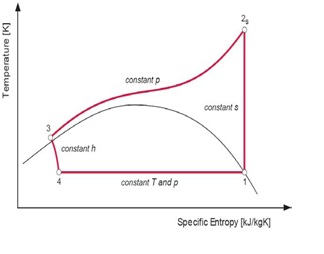
Figure 4: Ideal Lorentzen cycle
4 – 1:Heat absorption at constant subcritical temperature/pressure – i.e. constant T; 1 – 2s:Loss-less (isentropic) compression to supercritical pressure – i.e. constant s; 2s – 3:Heat rejection at constant pressure and gliding temperature – i.e. constant p; 3 – 4:Isenthalpic (adiabatic) expansion – i.e. constant h
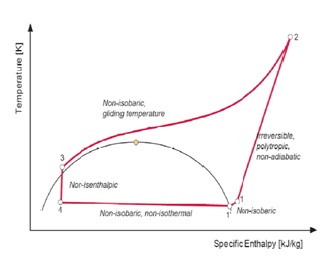
Figure5: Real Lorentzen cycle
4 – 1’:Non-isobaric (i.e. non-isothermal) heat absorption; 1’ – 1:Non-isobaric superheating of the suction gas; 1 – 2:Irreversible polytrophic non-adiabatic compression to supercritical pressure; 2 – 3:Non-isobaric supercritical heat rejection (gliding temperature); 3 – 4:Non-isenthalpic (non-adiabatic) expansion
The coefficient of performance of the modified Lorentz cycle is given in the equation below where Tm is mean temperature and To is temperature at entrance of the evaporator.
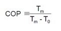
The term Lorentz efficiency is used for CO2 heat pumps for natural refrigerant instead of term Carnot efficiency used for conventional refrigerant heat pumps.
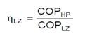
HP is term for real heat pump cycle while LZ is used for ideal Lorentz cycle.
Sanyo Eco Cute Split Cycle
Sanyo Eco Cute is using the split cycle refrigeration cycle in order to increase the performance of the heat pumps with 2 stage rotary compressors. In split cycle refrigeration some of the CO2 is expanded and bypassed to the compressor at an intermediate pressure state after leaving the gas cooler. The remaining part is then cooled by the bypassed refrigerant before entering the evaporator as shown in the figure below. The following figures show the split cycle refrigerant flow as well as the cycle drawn on ph diagram.
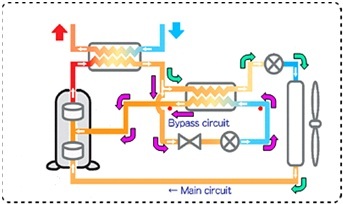
Figure 6: Split cycle refrigerant circuit.
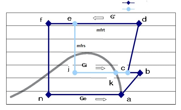
Figure 7: Ph diagram of split cycle
The mass flow rate in sub cycle is different from that of the main cycle and the mass flow rates can be defined as:
- mfrt:Total refrigerant mass flow rate (g/s)
- mfrm:Main cycle refrigerant mass flow rate (g/s)
- mfrs:Sub cycle refrigerant mass flow rate (g/s)
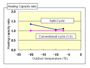
Figure 8: Heating capacity comparison.
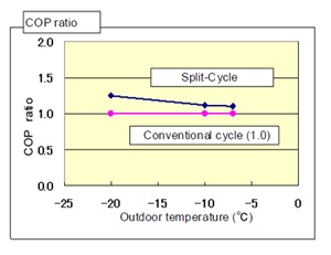
Figure 9: COP comparison.
Bibliography
1. Staub, J., Rasmussen, B.D., and Robinson, M., ‘CO2 As Refrigerant: The Transcritical Cycle,’ online posting. January 20,2004. http://www.achrnews.com/Articles/Feature_Article/97d657d6f5d5a010VgnVCM100000f932a8c0____.[accessed March,2011]
2. Lorentzen G., 1994: Revival of Carbon Dioxide as a Refrigerant, International Journal of Refrigeration, Vol. 17, No.5, p. 292-301.
3. Rieberer R., 1998: CO2 as Working Fluid for Heat Pumps. Ph.D. thesis, Institute of Thermal Engineering, Graz University of Technology, Austria.
4. REULENS, W., ‘Natural Refrigerant CO2 EDITED BY WALTER REULENS OCTOBER 2009 (Leonardo project)’ http://www.atmosphere2009.com/files/NaReCO2-handbook-2009.pdf.
5. Merino, S., Kobori, Y., and Ito, H., ‘The development of the 9kW CO2 Heat Pump water heater (3 phase 400V) for the European market’ http://www.nedo.go.jp/content/100080114.pdf