


The CO2 Heat Pump
R-744
Carbon dioxide is a natural refrigerant and is denoted by R744. Some of the most important things about this refrigerant are given below:
- Initially used in the early twentieth century as a refrigerant in marine and air conditioning systems
- Replaced by CFCs in the 1930s
- Search for new refrigerants after it is discovered that CFCs contribute to the depletion of the ozone layer and HFCs have a high global warming potential
- Work by Prof Gustav Lorenz in the 1990s proposed the "transcritical cycle" and brought renewed interest in R-744
- CO2 heat pumps used extensively in the Japanese market to supply cooling and domestic water heating
- Japanese systems brought to Sweden and adapted to operate in European climate with more focus on space heating
- Low critical temperature of 31.1oC
- 20 - 40 bar in the evaporator
- 80 - 130 bar in the gas cooler
Working cycle of R744
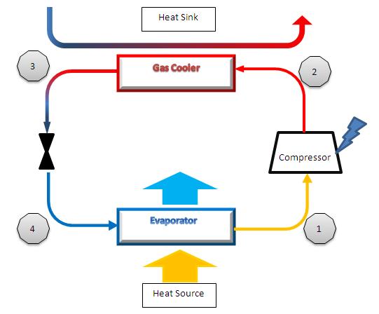
The figure shows different components of heat pump with R744
- Refrigerant CO2 leaves the evaporator in Liquid/Vapour form after having its temperature raised through a heat exchanger with the outside air. The vapour then enters the compressor.
- The liquid becomes a high pressure/high temperature vapour leaving the compressor and entering the gas cooler. The compressor requires an electrical input to increase the pressure of the CO2.
- Heat transfer with the heat sink across the gas cooler. This lowers the temperature and the pressure. It is still above the critical line.
- The working fluid is put through an expansion valve lowering the pressure of the liquid/Vapour. The CO2 is now at a lower temperature than the heat source and passes through another heat exchanger extracting heat from the outside air.
CO2 heat pump cycle
This transcritical cycle that makes CO2 unique, gives the refrigerant characteristics not seen in other refrigeration cycles. There is no sharp phase change on the heated side of the cycle where the condenser would normally exist in traditional heat pump cycles. The lack of phase change means that instead of a condenser in the CO2 cycle there is a "gas cooler". The working fluid is cooled through this gas cooler but doesn't drop below the critical point on the curve until after the expansion valve.
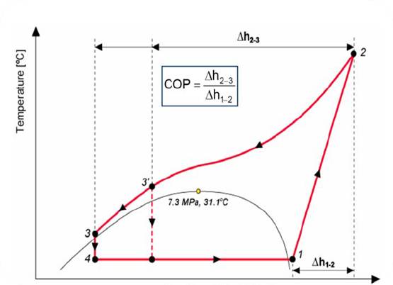
Temperature - enthalpy diagram
- Point 1 - 2: Compressor
- Point 2 - 3: Gas cooler
- Point 3 - 4: Expansion valve
- Point 4 - 1: Evaporator
The temperature drop through the gas cooler is known as the "temperature glide"!