


Sanyo Eco Cute System
The Sanyo Eco cute Heat Pump has been initially designed for the Japanese market in order to produce domestic hot water. With their traditional habit of hot bathing, Japanese people consume a significant amount of domestic hot water and CO2 heat pumps characteristics are ideally suited for this application.
In order to adapt this technology to the Swedish and the European market, Sanyo worked with a Swedish company to design a tank unit which will provide both space heating and domestic hot water. This entire project is based on this European version of the Sanyo Eco-cute system.
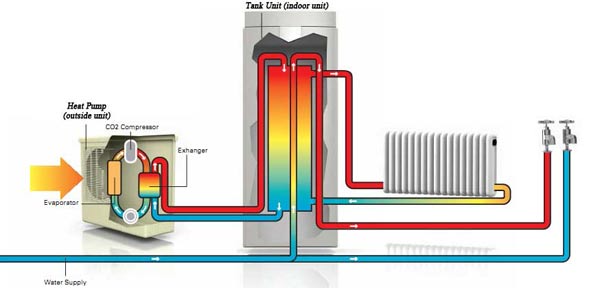
The Sanyo Eco Cute System consists of 2 parts:
- the CO2 air source heat pump
- the tank unit
The CO2 Heat Pump is installed outside to extract the heat from the surrounding air and transfer it to the tank unit by a water circuit. The tank then provides hot water for both domestic use and space heating.
The different version of Sanyo system
Different versions of the system have been successively commercialised. The first version has been released mainly in Sweden from 2004-2005. The heat pump had quite a lot of success since more than 3000 units have been sold in Sweden by Ahlsell, the authorised Swedish importer and distributer of Sanyo CO2 heat pump.
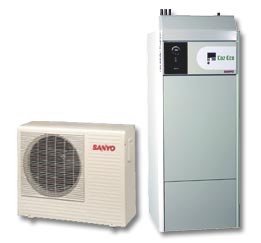
First version of the Sanyo Heat Pump
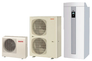
Second version of the Sanyo Heat Pump
The system was designed with a 4.5kW CO2 Heat Pump (SHP-C45DEN) and a buffer tank of 223 litres with a back-up Heater of 7 to 9kW (SHP-TH22DDN-SW or SHP-THEEDHN-SW). This System has been studied in Detail by KTH, Energy technology, in the lab of Division of Applied Thermodynamics and Refrigeration (a summary of the report is available here).
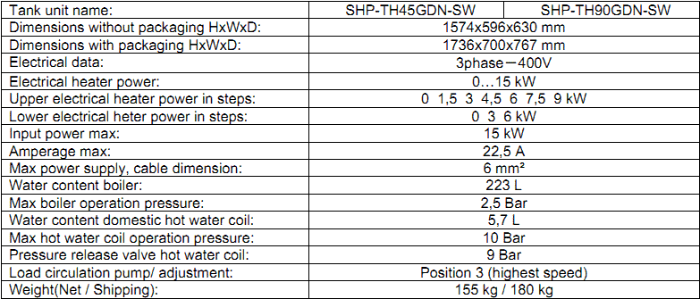
In 2007-2008, a new version of the system is commercialized: a new CO2 Heat Pump of 9 kW (SHP-C90GDN or SHP-C90GEN) is proposed with a new tank design, slightly improved according to the recommendation made in the KTH report (SHP_TH90GDN-SW or SHP_TH45GDN-SW or 3 phases). They tried to increase the stratification in the tank by adding an extra baffling plate at the bottom. The circulation of the water between the different parts of the tank would have also been modified (though it has not been verified). A second back-up electric heater is also added at the bottom of the tank.
Finally the control system of the Heat pump has been upgraded at least once in 2009 with new options on the controls added. The following presentation of the system concerns the last version of the device (manual 2009).
Description of the system
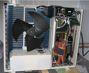
The outdoor unit
The 4.5 kW CO2 Heat Pump
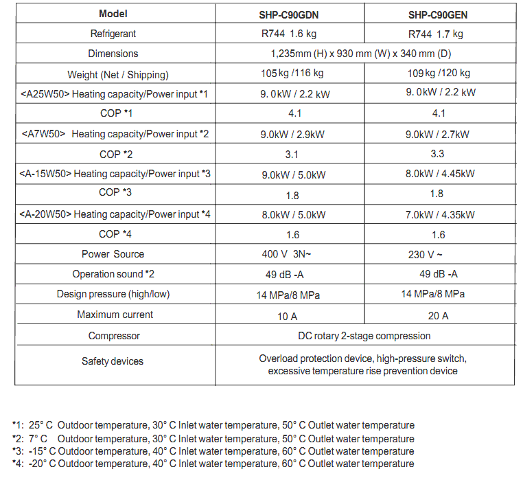
The 9 kW CO2 Heat Pump
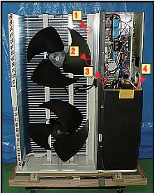
The outside unit contains the heat pump itself with the elements of the thermodynamic cycle cycle: an evaporator, a compressor, many expansions valves and a gas cooler (specific to the CO2 cycle)...
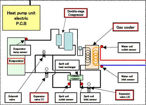
Some specificities can however be highlighted:
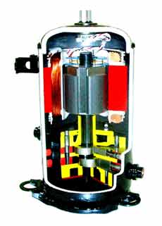
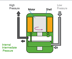
- A double stage scroll compressor enables an efficient compression at high pressure
- The cycle is split after the gas cooler. One part of the CO2 is expanded which sparks a decrease of this temperature. It is then used to cool down the main CO2 flow in an internal Heat Exchanger before its expansion. Thus the losses during the expansion are reduced significantly which increases the overall cycle COP.
The structure of the gas cooler is simple with only one heat exchanger. A water circuit comes from the tank unit, takes the heat from the CO2 and sends it back to the tank unit. The water flow is however controlled dynamically to optimise the cooling of the CO2 in the gas cooler and to reach the temperature required by the control system.
The performances given by the manufacturer as well as the main characteristics are given in the table below for the 9 kW.
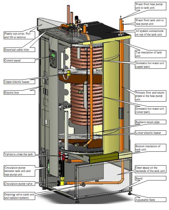
Tank unit
The tank provides some buffer storage between the energy delivered by the heat pump and the demand for domestic hot water and space heating. The tank can store 223 litre of water in the main reservoir. The water is drawn at the bottom of the tank unit, heated in the heat pump and released in the middle of the tank.
The main reservoir is connected to the heating system through a mixing valve. It draws the water from the top and the middle of the tank and eventually takes some water back from the heating system to adjust the temperature (diagram below).
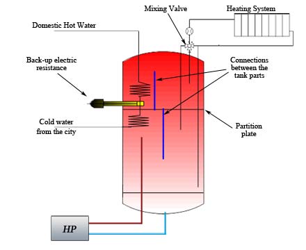
Inside the tank there is a partition plate at 1/3 of the height of the tank from the top. 2 tubes connect the 2 parts of the tank so that the hot water from the bottom circulates up and the cold water from the top circulates down. The temperature is monitored at the top and in the middle of the tank. An electric heater is used in the upper part to ensure the correct temperature at the top and another one is present in back up at the bottom when the heat pump can’t operate.
For hygienic reason, a heat exchanger is used inside the tank to heat the hot water: the domestic hot water is not mixed with the closed heating system circuit.
Control strategy of the system
The whole control of the system is quite complex and not straightforward to understand. A microchip operation monitors and controls the different parameters in function of the settings and the energy demand.
The following external sensors are used to control the system:
- A room sensor to measure the indoor temperature and adapt it in function of the demand.
- An outdoor temperature sensor next to the evaporator of the Heat Pump.
- An outdoor temperature sensor.
The temperature in the upper part of the tank is controlled by the system: a minimum and maximum value are specified in the settings. It enables a level of control over the domestic hot water temperature. The temperature in the middle of the tank is controlled in function of the demand and some minimum and maximum value. A sterilisation cycle is realised every 4 starts of the compressor: the flow of water coming through the heat pump is heated to 63-64°C and is maintained for a few minutes.
The mixing valve is used to get the correct temperature in the radiator. An efficient control can be applied to the system to get a comfortable indoor climate, with:
- A basement heating function.
- Day-to-day setting control to decrease the demand during the night or working hours.
- A summer limit enables to cut the radiator pump when the outside temperature is above a set point temperature.
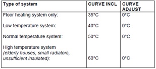
- To deliver the right temperature to the heater, the system uses one inclination curve with an adjustment. A lower outside temperature will induce an increase in the temperature of the water flow to the heater.
The slope can be adapted in function of the heating system of the house. The table below present the recommendation given by Sanyo concerning the choice of the settings in function of the type of heating system.
If the system can’t reach the required minimum temperature at the top of the tank, the upper back-up electric Heater will be used to follow the set point. The lower electrical power is normally not activated. It will be activated under the following circumstances:
- When no heat Pump is connected.
- When the outside temperature is too low and the heat pump doesn’t operate.
- When a Heat Pump fault occur.
The last version of the software enable to control the sterilisation cycle which is by default initiated every 4 starts of the compressor. More options enable to optimize the starts and stops of the compressor.
More information are given in the technical manual of the Sanyo Eco Cute system, available here: Manual 2009.
Bibliography
1. Pictures from the Sanyo website: uk.sanyo.com
2. Data from the Sanyo Eco Cute technical manual: Manual 2008