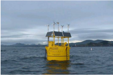
Point Absorber (AquabuOY - AquaEnergy Group Ltd)
|
Specifications
|
Source: AquaEnergy Group
|
The AquabuOY is a freely floating heaving point absorber, reacting against a submersed reaction tube (mass of water). The reaction mass is moving a piston assembly which drives a steel reinforced elastomeric water pump (hose pump). The hose pump pushes water on a high pressure level. An accumulator is used to smooth the power output and the pressure head is then discharged onto an impulse turbine to generate electricity. Grid synchronization is achieved using a variable speed drive and step-up transformer to a suitable voltage level.
Structural Elements
The structure is made of steel and can be built locally using standard construction techniques available in most shipyards. The structural elements were designed using finite element analysis.
Structural Elements
The structure is made of steel and can be built locally using standard construction techniques available in most shipyards. The structural elements were designed using finite element analysis.
|
Power Take Off
The hose pump delivers water into an accumulator to smooth the power output over the wave cycles. The water pressure is then discharged, driving a hydraulic impulse turbine. The power take off can be designed as a closed loop or open loop system. Regulation for the device is accomplished by slowly changing the pressure level in the hydraulic accumulator (the device cannot be rapidly adjusted to each wave that passes through). The lack of the power take-off system’s ability to rapidly modify the system will reduce its performance. |
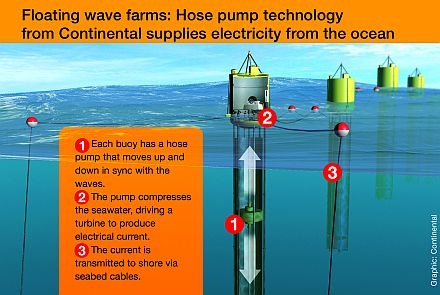
How AquabuOY works. Source: Continental
|
Mooring
The mooring consists of a slack-mooring configuration. Because the AquaBuOY is a small device (6 meter diameter), the mooring will be a more important cost component in the overall cost structure than for a larger device for a fixed power plant size. AquaBuOY mooring design requires generally 3 mooring lines per device. Slack moorings are commonly used in offshore applications where there is a need for the moored device to act freely without being affected by any vertical mooring forces. The AquaBuOY mooring system was successfully tested and proven in the early ocean tests in the North Sea with the predecessor IPS buoy.
Grid Connection
The AquaBuOY is synchronized with the grid using a variable speed AC-DC-AC converter and the voltage is increased with a step-up transformer. Flexible riser cables connect the devices to a junction box on the ocean floor. This aspect is standard and does not raise any significant concerns.
Installation
As the AquaBuOY is a relatively small device, it can be easily towed into a nearby port for major overhaul activities. In order to tow it into a nearby port, it would be required to be brought into horizontal position. This can be accomplished using a crane to bring the counter-reaction tube into horizontal position or by pumping air into sub-sea compartments.
Performance
Power Output comparison of wave tank testing and theoretical models developed by the company revealed an uncertainty in performance predictions. The root of the uncertainty may be that the system has only modelled the counter reacting tube as a mass without considering hydrodynamic interactions. The performance of this device will be limited by the capabilities of the power take off, which is only able to slowly adjust the device to the dominant wave period as outlined in the power take off section. The manufacturer also quotes a capacity per device of 250 kW, with an associated capacity factor of about 12% (assuming a 25kW/m wave climate). It is predicted that a capacity factor of around 40% could provide a near optimal economic value of electrical energy for this type of a device.
Survivability
The AquaBuOY has successfully solved the end-stop problem. If the hose pumps are elongated to a certain point, the piston assembly in the counter reacting tube will come into an area where the reaction tube widens. As a result, the water inside the tube is able to bypass the piston assembly and discharge without creating further dynamic stresses in the device structure. As such, it is an effective overload mechanism. The estimated life duration of this device is 20 years.
Operation & Maintenance
Remote monitoring and supervisory controls have not yet been designed. Ease of maintenance concerns come from the difficulty of assessing submersed components. These will likely include the hose pumps, piston assembly and check-valves. In order to carry out any repair on these components, the system will be required to be floated into horizontal position in order to access them. Turbo-machinery elements are likely accessible within the buoy hull. Alternative O&M strategies are under investigation by the manufacturer that would relieve some of these issues.