

| Technology Considerations |  |
Existing Projects Basic Functionality Support Structures
Operation and Maintenance Engineering Challenges Packing Density References
Existing Projects
There are two main projects currently in progress using the marine current turbine concept; The Hammerfest Strøm project in Norway, and the Marine Current Turbines project in Devon.
Hammerfest Strøm AS/ABB
Hammerfest Strøm AS, a Norwegian company, in collaboration with ABB, Rolls Royce and Sintef as well as Statoil developed the first grid connected marine turbine rated 300 kW. Installed on 17 September, 2003 in the Kval Sound. The prototype will supply 700 MWhr per year corresponding to electricity consumption by 35 Norwegian homes. The submerged structure weighs 120 tonnes and has gravity footings of 200 tonnes. Its 3-bladed turbine have been made in glassfibre-reinforced plastic and measure 10 metres from hub to tip. By rotating the propeller blades around their own axis at slack water when the current turns, the mill is ready for the reversing current (pitch control) keeping the nacelle fixed.
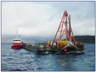
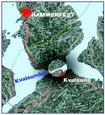
Figure: Deployment of the first grid connected marine turbine in Kval Sound, Norway.
Marine Current Turbines Ltd
Marine Current Turbines are currently field testing a submerged 300 kW tidal turbine. The turbine, costing £3m, has been built into the seabed about a kilometre and a half (one mile) offshore from Lynmouth. The single 11 metre-long rotor blade is capable of producing 300 kilowatts of electricity and will be a test-bed for further tidal turbines. It is hoped that the turbine can soon be connected to the national grid, and converted to twin rotors.
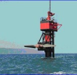
Figure: Deployment of the MCT turbine in Lynmouth, Devon.
back to top
Basic functionality
Marine Current Turbines use similar principles, as wind turbines, to harness the kinetic energy in moving water. Basically three steps are involved in the energy transformation:
- The turbine rotor is driven by the current. This converts the energy of the current into rotational energy of the shaft. The power is optimised by adjusting the angle between the rotor blades and the current.
- The gearbox converts the low rotational speed of the turbine shaft to the desired higher speed of the generator shaft.
- The generator converts its shaft energy to electric energy which is transmitted to the shore via a cable on the sea bed.
back to top
Support structure concepts
A key requirement for MCTs is to hold them reliably in place taking into consideration the harsh marine environment. Currently there are three options under consideration namely:
- Gravity Structures are massive steel or concrete attached to the base of the units to achieve stability by their own inertia.
- Piled Structures are pinned to the seabed by one or more steel or concrete piles. The piles are fixed to the seabed by hammering if the ground conditions are sufficiently soft or by pre-drilling, positioning and grouting if the rock is harder. In its simplest manifestation, the fixed piled structure may be a mono-pile (single pile) penetrating the seabed with the turbine fixed to the pile at the desired depth of deployment.
- Floating Structures provide a more convincing solution for deep water locations. In this case the turbine unit is mounted on a downward pointing vertical column rigidly fixed to a barge. The barge is then moored to the seabed by chains or wire ropes which hang in a centenary and may be fixed to the seabed by drag, piled or gravity anchors, depending on the seabed condition.
Monopile installation is an already established technique and seems to be the most favoured option. However this is currently limited to depths less than 50 m considering the capabilities of available jack-up barges.
back to top
Operation and Maintenance
It is important to have access to the turbine unit for maintenance. Two concepts have been proposed. The first is a hoist system based on a hydraulic unit, similar to the system used to raise marine platform legs. The other is a semi-submersible system which allows the rotor and power train to float on the water surface for access. The size and shape of the assembly is likely to make removal and replacement a difficult operation requiring calm sea conditions. For economic reasons it may be necessary to design the turbines such that it only requires minimum level of maintenance.
Hybrid photos of a single rotor MCT in operation (left) and maintenance modes (right)
back to top
Engineering challenges
- Cavitation: Relatively high velocities at the tips of the rotor blades are likely to lead to formation of cavities which may be difficult to avoid at all points along the blade. Eventhough design to avoid cavitation in hydraulic pumps and propellers is well understood a different approach may be necessary for marine current turbines because of its larger plane or rotor area. Cavitation is also sensitive to water depth and so some cavitation problems can be avoided by placing units in deeper water at potential cavitation sites. Research is therefore required to understand the problems of cavitation and whether prudent choices of blade profiles and materials can be made to avoid cavitation efficiency loss and damage problems.
- Biofouling: Many devices installed in the sea become artificial reefs, attracting a wide variety of marine organisms. These cover the structures and can cause significant fouling. Fouling of moving parts could affect the performance of devices. Several methods for preventing fouling have been proposed. These include the use of antifouling paints and sonic and ultra sonic systems. Both methods have their challenges and drawbacks calling for further research.
- Installation, Foundation and Moorings: The installation of marine current machines will present their own unique difficulties. Constructing foundations and installing equipment when the currents are running will be challenging. Only a few minutes of slack water can be expected each day. Scouring around the base of even temporary support structures, such as jack-up barges, can be significant even over very short periods. The construction of bridges in tidal stream areas (such as the Severn bridges in the UK) has been successful and similar construction techniques may be applicable to marine current devices. Most devices will have similar installation, foundation and mooring problems and so there is scope for generic research in this area.
- Packing Density: A good understanding of how many devices and of what size cause a significant effect on the marine environment and flow pattern can be used to suggest design guidelines for the sizing and placing of schemes. Some of the factors to be taken into consideration include seabed structure and depth, flow pattern and available area. This will help developers find suitable sites and planners to understand the implications of these farms. Currently, the engineering constraints set the upper limit for packing density before the resource degredation becomes and issue (see below).
- Turbulence: The velocity of the flow at a given location can vary greatly across the actuator area. This could lead to significant variations in loading across the actuator and associated fatigue and vibration problems. Understanding the turbulence levels is important not only to the siting of individual units (e.g. avoiding areas with strongly stratified flow) but can also inform the device design. The turbulent structure of the flow field is another important design driver affecting the design of components to resist fatigue. Design codes for marine current devices will refer to the likely design turbulence levels. Understanding what these levels will be is important to setting realistic limits to design. Prototype testing will be important in determining the importance of these issues. Turbulence measurements should also form part of resource assessments so that such measurements are taken at many sites and representative values obtained.
Packing Density
The packing density is one of the primary engineering challenges immediately facing marine turbine farm pioneers.
Packing density of Marine Current Turbine schemes should be selected in order to minimise turbulence as this could reduce the performance of turbines sited downstream. It should also maximise the energy capture from the tidal stream whilst reducing any barrier effect, which may deflect the tidal stream and reduce the energy available. Additional considerations are maintenance requirements and installation method.
During the literature search phase of the project, various theoretical methods for calculating the packing density of the turbine farms were identified. In the EC joule booklet each turbine is allocated an area of seabed related to the blade diameter; roughly 3 diameters in width and 30 diameters in length. This method predicts that the fluid velocity, after a distance of 30 diameters, will have returned to 99% of the free stream velocity. It then allows for a basic formula to be used for calculating the number of turbines at each site:

where
Other studies took slightly different approaches along the same principles, but the team felt it would be beneficial to research the possibility of creating a packing density model using computational fluid dynamics (CFD). After researching this area and a detailed conversation with an expert in the field, it was decided that a simplified numerical method as discussed above would be adopted. The main reason for avoiding the use of CFD was that no accurate information on the seabed topography at each of the turbine farms was available, effectively rendering any calculation valueless. In addition it was felt that the time and effort required to use CFD to obtain a useful model was out with the scope of this project.
back to top
References
-
BBC news (16 June 2003), Tidal energy turbine launches, BBC.
http://news.bbc.co.uk/2/hi/uk_news/england/devon/2992996.stm - Picture of functionality from Hammerfest Strøm AS/ABB at:
http://www.e-tidevannsen.ergi.com - Support Structure Concepts from Exploitation of marine currents in the Philippines
http://www.detini.gov.uk/cgi-bin/downutildoc?id=55
- Marine Current Turbines at:
http://www.marineturbines.com - EU Joule (1995), Marine Current Energy Extraction - Final Report, JOU2-CT93-0355.