
 Home
Home 
| The
Double-Multiple Streamtube Model (VAMCT) |
Froude's Momentum Theory for an Actuator Disk
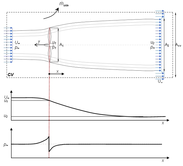
Froude’s actuator disk theory provides a simple, 1-dimensional approach to the problem of rotor modelling. Armed with the following assumptions consider an ideal rotor as shown below.
- 1-Dimensional analysis and disk is essentially a discontinuity moving through the fluid
- Infinitesimally thin disk of area A which offers no resistance to fluid passing through it as frictional forces are negligible compared with momentum flux and pressure changes (hence can make assumption 5)
- Thrust loading and velocity is uniform over disk
- Far-field is at free-stream pressure but far up and downstream
- Inviscid (thus irrotational), incompressible and isentropic flow
Since the disk acts as a drag device, and by assumption 1, the source of drag must be a pressure difference across the disk and this drag manifests itself as thrust loading along the axis normal to the disk. Rewriting N2 in terms of momentum:
| Eqn 1 |
A relationship between![]() ,u1,u2, Thrust (slowing the fluid) and Power
may be derived by consideration of the assumptions an N2. Noting
that assumption 1 states the disk is a discontinuity and that
the flow can be considered stationary, Bernoulli’s equation
and constant are not valid and may not be applied across the disk,
but may be applied from the far field to the disk in either direction.
,u1,u2, Thrust (slowing the fluid) and Power
may be derived by consideration of the assumptions an N2. Noting
that assumption 1 states the disk is a discontinuity and that
the flow can be considered stationary, Bernoulli’s equation
and constant are not valid and may not be applied across the disk,
but may be applied from the far field to the disk in either direction.
Placing a control volume around the disk extending far ahead to
the free-stream and considering that the disk serves to slow down
the flow, thus allowing mass conservation to define streamlines
(as the flow slows, conservation dictated the area increases):
Applying Bernoulli in valid regions:
| Eqn 2 |
| Eqn 3 |
| Eqn 4 |
Applying the axial momentum equation to a cylindrical control volume (CV) made by rotation of above control volume about the x-axis
 |
Eqn 5 |
dA is a unit vector normal to the integral element
(of unit area) of control volume in question; ![]() is the axial component of pressure forces acting on the c.v. Simplifying
this equation by assuming stationary flow (ie. a moving disk)
and noting that pressure forces on the ends of the c.v. are equal
(at
is the axial component of pressure forces acting on the c.v. Simplifying
this equation by assuming stationary flow (ie. a moving disk)
and noting that pressure forces on the ends of the c.v. are equal
(at ![]() )
thus
)
thus![]() and we have
and we have
| Eqn 6 |
Conservation of mass yields the following relationships
| Eqn 7 |
| Eqn 8 |
| Eqn 9 |
Which when combined with Eqn 6 gives the following relationship, as anticipated by (and in the expected form of) Eqn 1.
| Eqn 10 & by eqn 4 |
| Eqn 11 |
Thus the velocity at the actuator disk is the mean of the freestream
and far wake velocities.
Redefining the control volume to be co-incident with steamlines
around the disk, in other words ensuring no mass transfer out
of the c.v. except at the ends (as the fluid flows along streamlines
and cannot cross them). Thus recasting the axial momentum equations
as
| Eqn 12 |
And noting that the physics of the situation are the same, no
matter which c.v. is used, it is possible to declare the net pressure
force on the c.v. walls that follow streamlines must be zero.
By assumption 4 and referring to the new control volume, power
is equal to the rate of work, which is itself equal to the rate
of momentum transfer through the c.v and is given by
 |
Eqn 13 |
| Eqn 14 |
| Eqn 15 |
defining an axial induction factor a and by combining 15 &
11 ![]() well known result
well known result
| Eqn 16 thus |
| Eqn 17 |
| Eqn 18 |
Defining CP as power non dimensionalised by available power through disk area, and similarly defining CT forthrust,
 |
Eqn 19 |
 |
Eqn 20 and by 17, 18 |
| Eqn 21 |
| Eqn 22 |
Differentiating CP w.r.t. a yields
 |
Eqn 23 |
Which when equated to zero yields a theoretical maximum value of CP (16/27 at a = 1/3) for an actuator disk, known as the Lanchester-Betz limit after Frederick Lanchester and Albert Betz, of whom one worked with Ludwig Prandtl and the other was an all round genius (and a Brit).
This simple momentum theory is only valid for a certain range of values of a, above which physically unrealisable results are obtained as there occurs flow reversal in the wake and eventually the vortex ring state, so dreaded by helicopter pilots.
From here the derivation of the vertical axis turbine model can proceed and with rotational adjustments the horizontal axis model derivation may continue.
Rotational considerations
Assumption 5 states that the ideal rotor considered experiences
irrotational flow, which is intuitively incorrect unless there
is some sort of pre-rotator/stator arrangement to ensure an irrotational
wake, or a contra-rotating coaxial turbine. While these are both
feasible options, as assumptions they remove generality from the
model, and as such the model is developed assuming some amount
of rotation in the wake.
The Euler turbomachinery equation applied to an annular control
volume of infinitesimal dimensions is written in cylindrical (r,![]() ,x)
coordinates as
,x)
coordinates as
| Eqn 24 |
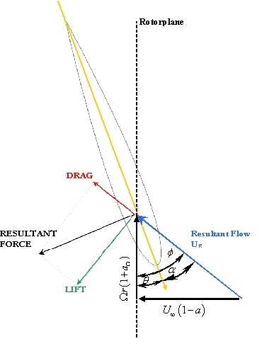
Where ![]() indicates
azimuthal component of absolute velocity U immediately after the
rotor and u1 is axial velocity through the rotor. The
velocity triangles in the figure below show the relation between
tangential velocity (due to rotation), absolute, normal and resultant
velocities for as section of the rotor. By equation 1, for a given
power and freestream velocity, rotational velocity component
indicates
azimuthal component of absolute velocity U immediately after the
rotor and u1 is axial velocity through the rotor. The
velocity triangles in the figure below show the relation between
tangential velocity (due to rotation), absolute, normal and resultant
velocities for as section of the rotor. By equation 1, for a given
power and freestream velocity, rotational velocity component ![]() post rotor degreases with an increase in rotor angular velocity,
Omega. In a similar manner as in the preceeding section, a rotational
or tangential induction factor a’ may be defined where
post rotor degreases with an increase in rotor angular velocity,
Omega. In a similar manner as in the preceeding section, a rotational
or tangential induction factor a’ may be defined where
| Eqn 25 |
| Eqn 26 and |
| Eqn 27 and |
 |
Eqn 28; with |
 |
Eqn 29 |
![]() is
the tip speed ratio (TSR) and (31) is the local tip speed ratio
at radius r.
is
the tip speed ratio (TSR) and (31) is the local tip speed ratio
at radius r.
 |
Eqn 30 |
Where ![]() is the angle between the aerofoil zero lift line and the resultant
velocity.
is the angle between the aerofoil zero lift line and the resultant
velocity.
References & Bibliography
| 1 | HANSEN, M.O.L., Aerodynamics of Wind Turbines : Rotors, Loads and Structure. 2001, London: James & James (Science Publishers) Ltd. pp. 152. ISBN 1902916069. |
| 2 | BURTON, T., et al., Wind Energy Handbook. 2001, Chichester, New York: John Wiley and Sons Ltd. pp. 624. ISBN 0471489972. |
| 3 | CHANEY, K. and EGGERS, A.J., Expanding Wake Induction Effects on Thrust Distribution on a Rotor Disc Wind Energy, 2001(5): p. 213-226. |
| The
Double-Multiple Streamtube Model (VAMCT) |
Go back to Contents