| Combined
Methodology |
Rationale
The objective of PART 2 of the methodology is to match the most appropriate technology to the resource for the most economic power output
By establishing and quantifying the site characteristics in terms of its bathymetry, tidal current velocity and seabed roughness, the most appropriate technology with respect to efficiency, power output and economics can be selected
The velocity distribution of the profile can be used to the following questions:
- What type of technology to use?
- What size of device?
- How many devices to put in the channel?
- Where should the devices be located?
- What is the lateral spacing between the devices?
- What is the SIF of the devices?
- What is the combined power output of the devices?
- How does economics affect the options?
- What is the environmental impact of the options?
- What is the appropriate distance along the length the channel that the next set of devices should be spaced?
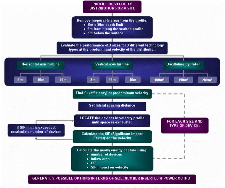
A procedure to answer these questions in a systematic manner has been developed and is shown pictorially in the flowchart and expanded upon further in point form.
back to top
Flowchart
The following flowchart defines the process that is necessary to match the appropriate technology to a a velocity distribution for a particular site. The procedure is a manual process that relies on several different tools. The tools can be substituted if the developer has access to more effective resources, such as power rating criteria or a higher quality of economics information.
The procedure to match the technology to the resource is demonstrated in the case study in the process section.

back to top
Process
The process outlined below is a more detailed explanation of the above flowchart.
Using the profile of the velocity distribution attained in part 1 of the methodology:
- Set a 30m depth limit and subtract inoperable areas from
the profile:
- 5m from surface
- 5m from seabed
- Evaluate the performance of 3 sizes for 3 different technology
types for that particular velocity distribution and allocate
power ratings to devices
- Calculate the NUMBER of devices that fit into channel.
- This is a function of the area, velocity, depth, efficiency
& no of devices and limited by the recommended extraction
value
- LOCATE the devices in the appropriate areas of the velocity
profile
- For each technology and size option:
- insert 1 device into constrained space - Repeat process:
- insert 2nd device into constrained space
- calculate the SIF (Significant Impact Factor) on the velocity
- Continue to process until space is exhausted or SIF
is exceeded
- Calculate the total POWER output using the number of devices,
the inflow area and the velocity distribution
- Horizontal Axis Turbine; Diameter: 5m, 7m, 10m
- Vertical Axis Turbine; Height: 8m, 12m, 16m
- Oscillating Hydrofoil; Area: 100, 150 , 200 - Generate 9 possible options in terms of size, number inserted
& power output
- Assess most suitable technology by considering power output
in conjunction with economics & environmental
impacts for a particular velocity profile
- Repeat entire process by considering the power output for
another profile a specified distance along the channel
- Repeat by generating profiles and their potential power outputs along the channel and summing the value to calculate the power output for the entire length of channel
- calculate the SIF (Significant Impact Factor) on the velocity
back to top
Tools
Click on the icon  to access each tool and click the title to access
the 'explanation and theory' behind each tool.
|
||
| These tools are able to calculate the power output at a particular velocity for a variety efficiencies, rpm, torques and sizes | ||
 |
||
 |
||
 |
||
 |
|
|
| This tool is used assess and calculate the significant impact on velocity due to the extraction of energy taking into accounts efficiencies, number of devices inserted and sizes |
| Combined
Methodology |
Go back to Contents

 Home
Home 
