There are a variety of technologies used for electricity storage. It is useful to differentiate the options by grouping them into their particular characteristics and useful applications.
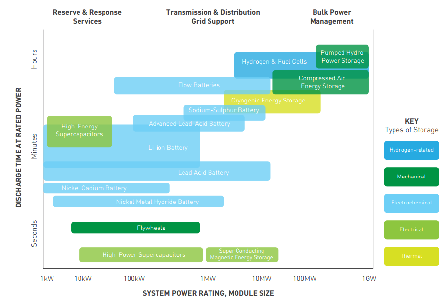
A common way of categorising storage technologies is by their power ratings and discharge times.
Those with lower power ratings and shorter discharge times are labelled as suitable for helping with power quality and reliability whereas options with larger power ratings and energy capacities are termed as “Energy Management” options.
The figure below shows how a variety of storage options have been compared. It should be noted how batteries can vary significantly in terms of their power ratings. The key also differentiates the technologies based on their physical characteristics. Cryogenic Energy Storage is better known as Liquid Air Storage and will be discussed in further detail below.

For Industrial plants looking to become autonomous from the grid it is suitable to focus on the larger scale technologies used for energy management. What follows is a brief description of a few of these options looking at their distinguishing features.
Compressed Air Energy Storage works by splitting up the compression and expansion stages of a traditional gas turbine cycle into two separate processes. Energy is stored in the form of elastic potential energy of compressed air. When demand is low, the surplus electricity may be used to compress air into a tight space. This space is usually situated in large underground caverns and acts as the energy store. To extract the energy, the air is drawn from the space, heated and expanded through high and low pressure turbines which are connected to generators to produce electricity.[2]
Liquid Air Energy Storage consists of an air liquefier to charge the system using electricity. Air is drawn into the liquefier, cleaned and cooled to sub-zero temperatures resulting in the air being liquefied. To give an idea of the scale of the compression, 700 litres of ambient air becomes 1 litre of liquid air which is stored in a low pressure tank. This tank is the energy store. When required, liquid air is drawn from the tank and pumped to high pressure with the help of adding stored heat from the liquefier. This high pressure gas is used to drive a turbine which is connected to a generator producing electricity (which is similar to the end of the compressed air process). Highview Power Storage is a UK based developer of Liquid Air storage plants and completed its first test plant in 2011 with a power rating of 350kW and energy capacity of 2.5MWh – giving a discharge time of over 7 hours. The company claims that future projects scaling up to beyond 50MW/200MWh are possible.[3]
Batteries vary greatly in their suitability for energy management purposes. The basic layout of a battery includes at least one electrochemical cell consisting of an electrolyte (in the form of a liquid, paste or solid) together with positive and negative electrodes (anodes and cathodes respectively) – often called terminals. The electrolyte separates the cathode and anode. When connected in a circuit, a chemical reaction produces positive ions and electrons (negative) at the cathode. The positive ions travel through the electrolyte to the anode and the electrons flow round the circuit to reach the anode. This flow of electrons is effectively the battery “discharging”. It’s possible to reverse the reaction by supplying a current across the terminals effectively resetting the battery chemicals to their original state.
Different kinds of batteries use different chemicals. For example, Sodium Sulphur batteries have molten liquid sulphur at the anode and molten liquid sodium at the cathode separated by a solid beta alumina ceramic electrolyte. Japan has recently seen a number of sodium sulphur battery banks used for large scale applications.[4] For example, the Rokkasho-Futamata Wind Farm has a 51 MW wind generation capacity which uses a sodium sulphur battery reserve of 34MW.
Flow Batteries differ from electrochemical batteries as the chemical reaction takes place inside a chamber and the electrolytes are stored in external units. Energy and power are independent of one another. The energy storage capacity is determined by the amount of electrolyte used and the power rating by the active area of the cell stack. Examples of flow batteries include Vanadium Redox and Zinc Bromine.
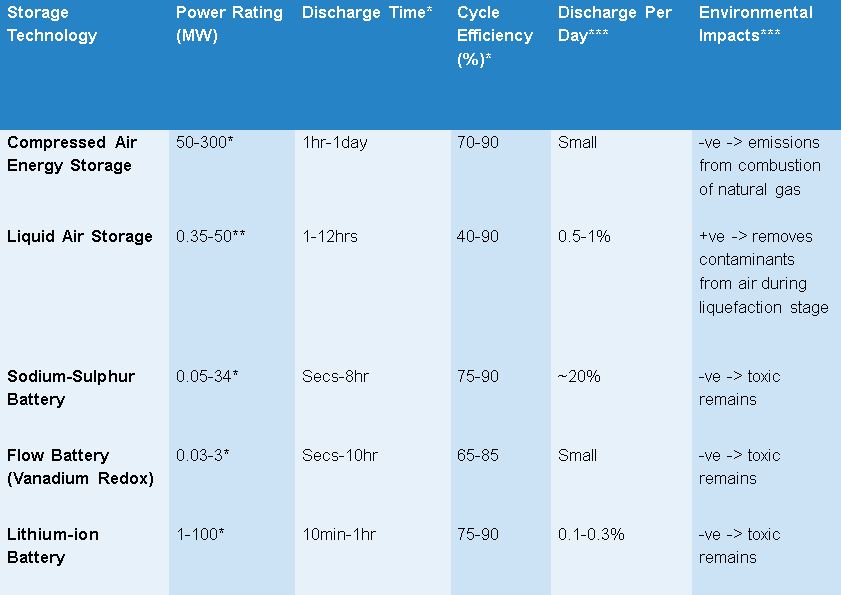
The table below indicates the more important characteristics of these storage technologies. It should be noted that the majority of academic papers publishing similar tables tend to use large ranges indicating the relatively immature stage of current installed projects. These parameters are defined in greater detail in the “Tool Inputs” section.

The stars next to the numbers /column titles indicate where that particular estimate is coming from.
* Centre For Low Carbon Futures – “Pathways for energy storage in the UK”(2012) (p. 21)
**Highview website: http://www.highview-power.com/
***Chen, Haisheng, et al. "Progress in electrical energy storage system: A critical review." Progress in Natural Science 19.3 (2009): pp. 307-308
References
[1] Centre For Low Carbon Futures – “Pathways for energy storage in the UK”(2012) (p. 22) http://www.lowcarbonfutures.org/sites/default/files/Pathways%20for%20Energy%20Storage%20in%20the%20UK.pdf
[2] Ibid. p.19
[3] Highview Brochure (2014) – available for download from Highview website - http://www.highview-power.com/
[4] Chen, Haisheng, et al. "Progress in electrical energy storage system: A critical review." Progress in Natural Science 19.3 (2009): pp. 291-312