Dynamic Voltage Restoration
In this project, we have discovered that a dynamic voltage restorer (DVR) could be used to protect the site from voltage disturbance from the GRID. A voltage dip is a serious and ongoing problem for GSK and can be caused by faults on the distribution network such as lightning strikes, load changes or contact between line conductors etc. Some of the factors listed below can affect he magnitude, shape and duration of the voltage dip;
· The type of fault
· The impedance
· Location of the fault on the network
· Connections to the transformers and the loads
· Coupling between phases
· Protection schemes used in the network
The DVR is a quick and efficient solution to voltage dip problems. The DVR is a power electronic based device that gives out a three-phase voltage source that adds to the incoming voltage during an event such as a voltage sag. The DVR then restores the supply voltage to the pre-conditions. In order to implement the DVR, a study must be carried out to realise its potential and how it can be implemented into the site along with a suitable control strategy. The device uses static electronic components, and can be connected in series to the distribution network circuit. The device once connected can provide a controlled voltage source to bring the supply back to normal conditions.
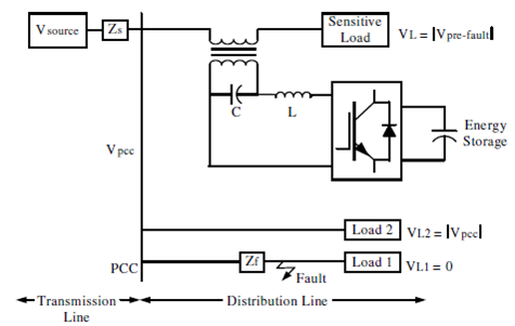
The diagram above displays the location and the use of a DVR on the a distribution network. In this case a fault occurs on line 1 which feeds to load 1, and the voltage sags or dips. Load 2 then will experience a dip with respect to the magnitude equal to that of the voltage at the PCC end. In this diagram the sensitive load is protected by the DVR and will therefore not subject to the problems felt at load 1.
The dynamic voltage restoration is based on injecting AC voltages in series with the incoming three phase network, which will in turn improve the quality of the voltage through its magnitude, wave-shape and phase shift. The main components of a DVR include an injection transformer, a harmonics filter, a DC-DC boost converter and an energy storage device. Under voltage dip conditions, the energy storage device supplies energy to the distribution network to compensate for the drop in voltage. The DC booster gives more energy to the DC link to make sure that the link voltage is maintained at a constant level during the voltage drop period. During this time the voltage source inverter (VSI) will produce voltages needed to bring the voltage conditions back to normal. The filter is used to remove any harmonics created by the inverter, and the injection transformer is used to boost and match the injected voltage to the system.
Basic configuration and components of DVR
Energy Storage unit - For the DVR to supply a needed voltage onto the system in order to restore the load supply voltages there needs to be a source of energy. There are two main types of configurations; one which uses stored energy and the other where energy is taken from the supply, through a shunt converter. Energy Storage is needed to provide real power to the load when there are large voltage dips. Examples of energy storage can be batteries or capacitors banks.
Inverter Circuit – The voltage Source Inverter (VSI) is simply an inverter built into the DVR. This converts the DC voltage from the energy storage supply into a three phase A C voltage. He VSR can be a 3-phase 3 wire or 3 phase 4 wire configuration. The inverter is rated low in voltage and high in current due to the use of step-up injection transformers. The inverter switches are operated using sinusoidal pulse width modulation. The voltage dips on the grid network are unbalanced and the VSI will cope with unbalanced switching functions for three phases, by coping with each phase separately. Having said this, a voltage dip on one phase may create a voltage rise on another phase, and therefore the VSR must be able to cope with this problem. Another configuration of the DVR is the use of a multi-inverter system, which adds the voltage of a single cascaded inverter in series which will allow for the inverter voltage. This method removes the need for an injection transformer.
Series Injection Transformer – The injection transformer plays an important role in maintaining maximum reliability and effectiveness of the restoration. The injection transformer, injects voltages in series with the incoming supply voltages in order to solve voltage dip problems. The injected voltages are brought into the distribution system through an injection transformer connected in series with the distribution feeder. In order to understand how the system works and how it can be integrated, the parameters of the transformer are needed. For example;
- The MVS rating
- The primary winding voltage and current ratings
- The turn-ratio (secondary winding characteristics)
- Short circuit impedance
However in order to evaluate the above parameters of the transformer, some of the specifications of the system need to be determined, for example;
- The energy storage capacity
- The control procedure and strategy
- The design of the harmonic filter system
- The MVA rating of the load which is being protected (GSK site)
- The switching devices being used
- The maximum voltage drop across the transformer
- The characteristics of the voltage dips/swells
Three single-phase injection transformers are used to inject the needed voltage during a voltage dip/spike and can be connected to the distribution line with star/open star windings or delta/open star windings. The star winding gives an injection of positive, negative and zero sequence voltages and the delta gives an injection of positive and negative sequence voltages.
Passive Filters – The filter component for the DVR can be placed either on the high-voltage side or the inverter side of the series injection transformer. The inverter side filter has an advantage over the high-voltage side because it is located closer to the harmonic source. The passive filter prevents high-order harmonic currents coming from the VSI and therefore its impact on the injection transformer current rating can be neglected. The harmonic currents will be prevented from penetrating into the series transformer and therefore reducing the stress on the transformer. When the DVR acts as a source the use of the filter inductor causes voltage drop and a phase shift in the inverter output, which in turn can affect the control scheme of the DVR. When the filter is located on the high voltage side of the transformer, high order harmonic currents will be able to pass through the transformer, thus necessitating a higher rating of the transformer. The problem with both configurations is that the filter capacitor will cause an increase in the inverter rating.
Furthermore, there are some compensation strategies that are used within the DVR and the injection of the voltage at the transformer. These methods are listed below;
1) Pre-Dip Compensation – The DVR injects the missing voltage between during-dip and pre-dip voltages into the system and therefore must compensate for both magnitude and angle. It is good practice to reach the same load voltage as the pre-fault voltage.
2) In phase Compensation – The injected voltage is in phase with the supply voltage, however the load voltage and pre-fault voltages are different. It is important in any power quality issue that the constant magnitude of load voltage is given. This compensation technique is good for loads that can hold phase angle jumps.
3) Minimum Energy Injection – this describes the way to maximise the active power supplied from the grid, which in turn holds the apparent power at a constant level while decreasing the reactive power (by increasing the reactive power supplied by the compensator.
In order for the DVR to serve its purpose, there must be a method by which to detect the voltage dip on the network. It is important to measure the start point of the dip, the end point, the overall depth and the phase shift. There are four main ways in which to detect a voltage dip, which are as follows;
1) Peak Value Method – this is the simplest design where the supply from the network is monitored by looking at the peak of the supply voltage and comparing it to a reference voltage. In this way the controller will detect a voltage dip and then activate the transformer.
2) Root Mean Square - In order for the system to calculate the end point of the fault, the start can be pre-defined at the first point of Vrms when it drops below 0.9pu. The end point can be found by looking for a time period where the Vrms drops below 0.9pu for a minimum of half a cycle.
3) Fourier Transform – this method is achieved through the orthogonal decomposition of the power signal. The FT is applied to each supply phase and therefore the system can detect the magnitude and phase of each of the frequencies of the waveform.
4) Space vector method – The supply three phase voltages are changed into a two dimension voltage output, which can be transferred into magnitude and angle. Any change in the quantities shows an event, which can be compared to a reference quantity.
http://www.ripublication.com/aeee_spl/aeeev4n6spl_17.pdf
http://www.ijeei.org/docs-16908489204d9aa8d956d52.pdf