Energy Storage Selection
Ibrahim et al., (2008) compared different types of energy storage based on their characteristics using the following criteria:
1. Storage Capacity: The quantity of available energy in the storage system after charging.
2. Discharge Rate: The rate at which the stored energy is discharged to meet demand during peak periods.
3. Efficiency: The ration between released energy and stored energy
4. Cycling Capacity: The number of times the storage unit can release the energy level it was designed for after each recharge.
5. Cost: Analysis showcasing total gains exceeding total expenditure. Two major factors involved are Capital Investment and Operational Costs.
6. Self Discharge: The portion of the energy that was initially stored and which has dissipated over a given amount of non-use time.
7. Mass and Volume Density of Energy: the maximum amounts of energy accumulated per unit of mass or volume of the storage unit.
The upshot of their analysis was the recommendation of Thermal Energy Storage (TES) and Compressed Air Energy Storage (CAES) for large scale systems while Lead Batteries and Superconducting Magnetic Energy Storage (SMES) were recommended for small scale systems. The choice of most optimum type of energy storage was premised on the aforementioned recommendation for large scale systems. Also, a novel storage technology, Liquid Air Energy Storage was investigated.
Advanced Adiabatic Compressed Air Energy Storage System (AA-CAES)
There are currently two existing Compressed Air Energy Storage (CAES) plants in the world. The Huntorf Plant in Germany established in 1978 and the McIntosh Plant in Alabama, United States established in 1991. The limitation of these plants is the incorporation of fossil fuels (mainly natural gas) to increase the temperature of the compressed air exiting the air chamber so as to improve the efficiency of the expansion process in the turbine. This process results in CO2 emissions which undermines the objective of a net zero carbon energy generation. The drawbacks of these existing plants culminated in research and development of an Advanced Adiabatic Compressed Air Energy Storage System which incorporates a Thermal Energy Storage (TES) with the Compressed Air Energy Storage (CAES). This type of storage is otherwise known as a CAES-TES system and has been stipulated to have a total energy conversion efficiency of about 70% (Madlener and Latz, 2011). A novel plant with this technology called ADELE is under construction in Germany.
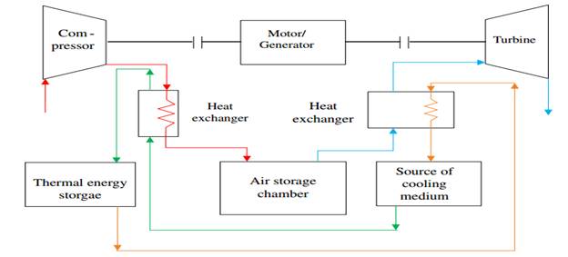
Fig. 1: CAES-TES System
The compressor uses surplus electricity generated to compress atmospheric air into the Air-Storage chamber. The heat from compression is passed through a heat exchanger where it is extracted and stored in the TES. During periods of peak demand where power generated is inadequate, the stored compressed air is passed through a heat exchanger where the temperature is heated with the stored heat from compression before expansion in the turbine which drives a generator.
Modelling of CAES-TES for the Site
The modelling of the CAES-TES system was carried out using Microsoft Excel with the following assumptions:
Compressor efficiency = 0.81
Compressor Output (Volumetric Efficiency) = 2810 m3/min = 168600 m3/hr = 46.83 m3/s
Working Pressure of Compressor = 150 psi = 10.342 bars
Turbine efficiency = 0.87
Total Energy conversion efficiency = 0.7
The charging and discharging analysis were carried out on an hourly basis for a 28-day period due to the fact that, the energy demand for the site is approximately the same over a long term period.
Charging rate per hour (kW) = Net Energy Export * 0.81
Discharging rate per hour (kW) = Internal Energy of Compressed Air * 0.86
The results from the modelling indicated a peak charging hourly value of 210,322kW (210MW) which determines the size of the air storage chamber. The air storage chamber can be of two types, either an air storage tank or an underground salt cavern. However, lower pressure underground gas storage in bulk quantities is much less expensive than above ground storage in high pressure containers (Maton et al., 2013). Hence for this project, an underground salt cavern is recommended as a cost-effective medium for storing compressed air.
The energy stored in the underground cavern is dependent on the thermodynamic properties of pressure, volume, temperature and polytropic index ‘n’.
For an Adiabatic Process, n = 1.4
Energy per unit volume ![]() ---- (1)
---- (1)
Energy per unit volume W = 210322 * 103 / 46.83 = 4491.2 * 103 J/m3
Pmin = 10.342 * 105 N/m2
Solving for Pmax; From equation (1), Pmax = 174.176 * 105 N/m2
Recall: ![]() ---- (2)
---- (2)
Vmax = 168,600m3/hr; From equation (2), Vmin = 22,432m3/hr
Results and Discussion
The assumptions and equations stated in the modelling procedure were derived from values extracted from on-site data where the project is to be executed and also, from standard values and formulae culled from AA-CAES research in the literature. The CAES-TES system will charge at maximum specific volume (Vmin) and minimum pressure (Pmin) until it reaches full capacity at maximum pressure (Pmax). The volume at maximum pressure (Pmax)is the required volume of the air storage chamber (Underground Cavern). The working pressure of the compressor (Pmin) is 150psi, and the volumetric efficiency at maximum pressure (Pmax) is 22,432m3/hr.
Since, the modelling was carried out on an hourly basis, the specific volume is expressed in terms of hours. Hence, the maximum quantity of air that can be stored in the underground cavern at any given hour is 22,432m3.