|

|
Selection of mooring lines
The floating platform is tethered to the riverbed via mooring lines. The main role of the moorings is to maintain the system on station by not allowing extreme horizontal and vertical excursions and to be placed in a way that contact with other mooring lines of adjacent stations or with the electrical transmission cables will be avoided. We used a mooring system comprised of 4 catenary mooring lines. Each line is attached to one corner of the platform, while its other end is anchored on the river bottom through a drag-embedment anchor [1].
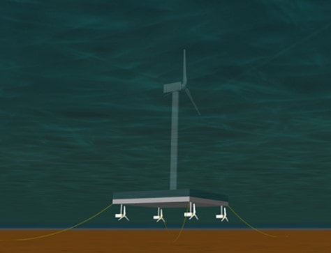
Figure 1: Mooring lines of HAPI system
The criteria on which we were based to select the characteristics of the mooring lines are listed below:
1. A spread mooring system was chosen because it best obstructs the horizontal excursions of the platform and allows large compliance.
2. Catenary mooring lines were selected due to their suitability for shallow waters, which derives from their capability of providing their restoring forces through their suspended weight and from their subjectivity only to horizontal forces [2]. This is a significant difference in comparison to the taut lines, since the latter must be able to withstand vertical forces, as well.
3. The material of the line is studless chain R4 grade. It’s the most common in such constructions, primarily due to its low weight and high safety comparing with the wire rope [3].
4. The nominal diameter of each line was set to be 50mm. This was based on the platform weight, the water depth and the wave characteristics.
5. In order to ensure that the lines are able to withstand the exerted tensions on the platform without deformation or breaking, we calculated some of the important parameters which are shown on the following table and then tested their durability in Orcaflex software.
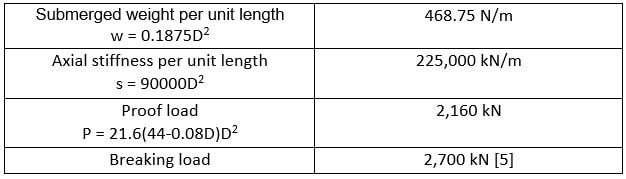
Table 1: Mooring line parameters
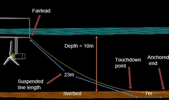
Figure 2: Mooring line design in Orcaflex software
In the next table the tensions of all mooring lines on their fairlead are calculated through Orcaflex. As we can notice, all the line tensions are safely below their breaking load which means that the mooring lines can successfully hold the system in place.
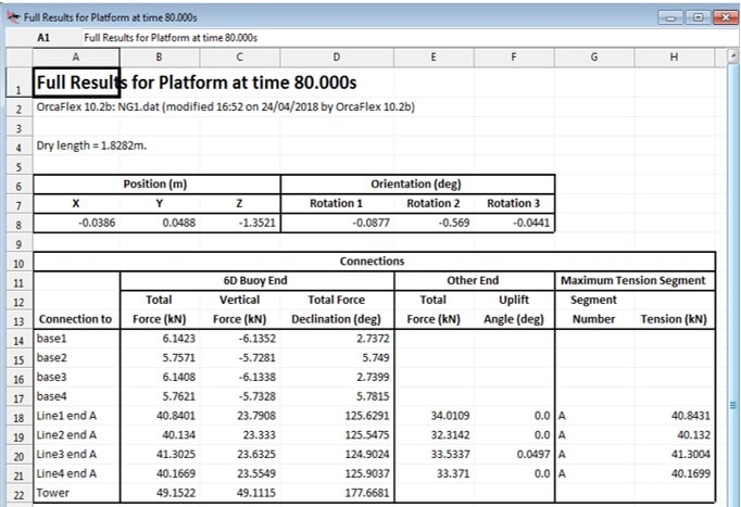
Table 4: Line tensions under normal operation conditions obtained from Orcaflex
References
[1] Zanuttigh, B., Martinelli, L. and Castagnetti, M. (n.d.). Screening of suitable mooring systems. Universita di Bologna, Aalborg University.
[2] Wang, T., Yang, L., Xu, Z. and Liu, J. (2013). Design and Comparison of Catenary and Taut Mooring Systems for New Concept FPSO IQFP in Shallow Waters. Applied Mechanics and Materials, 353-356, pp.2670-2675.
[3] Professor Tao, L., (2017-2018). Riser and Mooring Lines (NM521/NM958). Dept of Naval Architecture, Ocean and Marine Engineering, University of Strathclyde.
[4] Anchors and Chains Factory. (2018). Studless Offshore anchor chains on stock. [online] Available at: http://akfanchorchain.com/products/chains-accessories/studless-offshore/ [Accessed 5 May 2018].
[5] BillBoard Engineering Co. Anchor Chain-Proof and Breaking Loads.
|
|
STRATHCLYDE UNIVERITY
16 Richmond Street Glasgow G1 1XQ Scotland, United Kingdom Phone: +44 141 552 4400 https://www.strath.ac.uk © Copyright 2018 |

|