|
|
1. Introduction
The main aim of this analysis is to check if the whole concept sustains the internal and external forces. The feasibility of the design depends on the behavior of the structure in the water. The model that was simulated in Maxsurf software will be thoroughly described afterwards and it can be seen in the figure below. The blades have not been designed due to software limitations but their weight has been included in the total weight of the turbines.
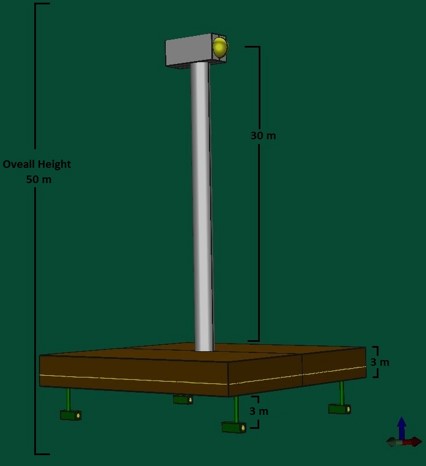
Figure 1: General Configuration
|
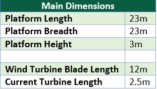
Table 1: System dimensions
|
More detailed information can be found in the Design Concept part.
2. Methodology
a. Theory behind the analysis
Every floating body experiences an upward force from the Archimedes’ principle. This force is called Buoyancy force. It is equal to the weight of the fluid displaced by a fully or partially submerged body. It acts directly in the centre of the fluid displaced [1].
The most important rule for this concept is to have enough buoyancy force to carry all the weight groups by itself without sinking. In this sense, the stable equilibrium can be achieved when the total weight [Wind + 4x Current turbines + Platform] is equal to the buoyancy. If the weight exceeds the buoyancy, the object will sink. However, if the buoyancy exceeds the total weight of the body, the object tends to rise.
The most important rule for this concept is to have enough buoyancy force to carry all the weight groups by itself without sinking. In this sense, the stable equilibrium can be achieved when the total weight [Wind + 4x Current turbines + Platform] is equal to the buoyancy. If the weight exceeds the buoyancy, the object will sink. However, if the buoyancy exceeds the total weight of the body, the object tends to rise.
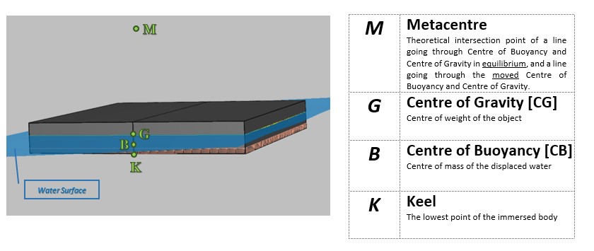
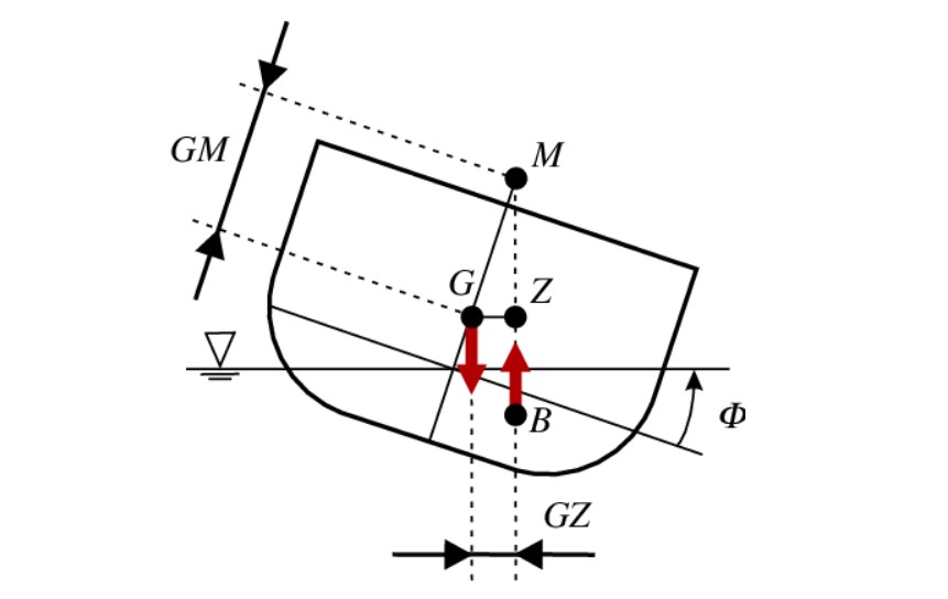
Figure 2: Hydrostatic Parameters
Every object tends to rotate under external force application. This rotation changes the underwater shape of the immersed object. Consequently, the volume of the displaced fluid is changed and the position of centre of buoyancy along with it. This causes rotational moment. For static stability of a floating body, it has to be able to return to its original position after small change in position of displacement caused by external forces – restoring force.
This is a result of a centre of buoyancy change because the underwater shape of underwater body changes.
This is a result of a centre of buoyancy change because the underwater shape of underwater body changes.
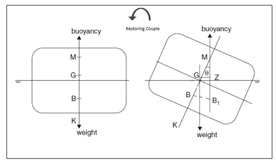
Figure 3: Stable Equilibrium [3]
There are three conditions of the equilibrium based on the Metacentric height [GM] analysis [2]:
The main aim of the hydrostatic analysis is to find the balance of the component in order to achieve stable equilibrium condition. This check was completed by computation of the equations below.
GM is called Metacentric height. Basically, it is a parameter which measures the initial stability of a floating object.
- Stable Equilibrium: The body returns to the original position
- Unstable Equilibrium: The body continues to change its position and it can easily capsize
- Neutral Equilibrium: The object keeps staying in the displaced position until a small change disturbs it and tends to return to initial position or opposite – further away
The main aim of the hydrostatic analysis is to find the balance of the component in order to achieve stable equilibrium condition. This check was completed by computation of the equations below.
GM is called Metacentric height. Basically, it is a parameter which measures the initial stability of a floating object.
- KB is the vertical distance from the Keel to the CB
- BM is the vertical distance from the CB to the Metacentre
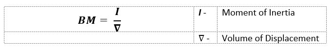
Since the shape is very basic, the moment of inertia can be calculated from the following equation based on Length [L] and Breadth [B] of the platform:

- KG is the vertical distance from the Keel to the CG – equal to the barge height
3. Analysis and Results
In order to achieve successfully working product, the HAPI concept has been designed and analysed in Maxsurf software which are described below. Moreover, the stability analysis has been performed and the results were compared to the existing classification body regulations – DNV GL and IMO [4]. In this project Maxsurf Modeler and Maxsurf Stability were used.
a. Maxsurf analysis
The pictures below show the look of the HAPI concept designed in Maxsurf Modeler. The DWL means Draught Waterline. The Designed draught of the platform is 0.8m but after addition of ballast tanks for better stability the Draft Amidships is 1.17m.
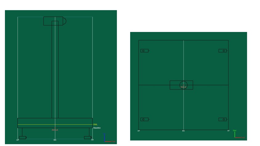
Figure 4: Side and top view in Maxsurf
An addition of ballast tanks had to be applied in order to achieve better stability of the structure. The tanks are filled up with Concrete with density of 2.08 t/m^3.
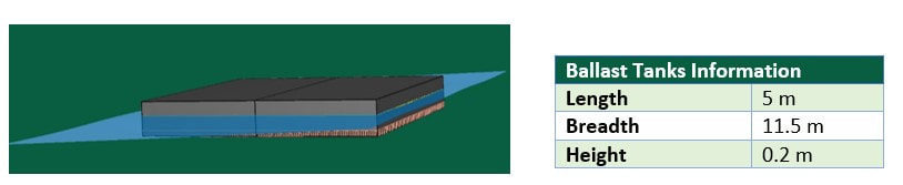
Figure 5: Ballast Tanks View and information
b. Dead load
All the weights of the structure components are listed below in the table in order to calculate its stability. The Wind and Current turbines weights include full electrical and mechanical equipment provided by the supplier. Moreover, the Platform weight includes the weight of Stiffeners and Girders.
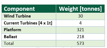
Table 2: Components' weights
c. Hydrostatic results
The results from the stability analysis are combined in a table below.
Note: All the measurements are according to the coordinate system with the following origin:
X = 0 at MS (Midship), positive forward
Y = 0 at centre line, positive to starboard side (sometimes marked with “S” or “P”).
Z = 0 at base line of the platform, positive upward.
Note: All the measurements are according to the coordinate system with the following origin:
X = 0 at MS (Midship), positive forward
Y = 0 at centre line, positive to starboard side (sometimes marked with “S” or “P”).
Z = 0 at base line of the platform, positive upward.
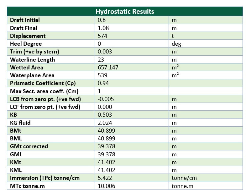
Table 3: Hydrostatic Results
d. Large angle of stability
The Statical Stability Curve (GZ curve) is one of the most important tools for measuring the stability of a floating object. There are several features to be outlined [3]:
- The largest steady heeling moment the platform can withstand without capsizing
- Vanishing angle – when the GZ becomes zero, is the largest angle that the platform can return after the loading is removed
- Important for freeboard and reserves of buoyancy
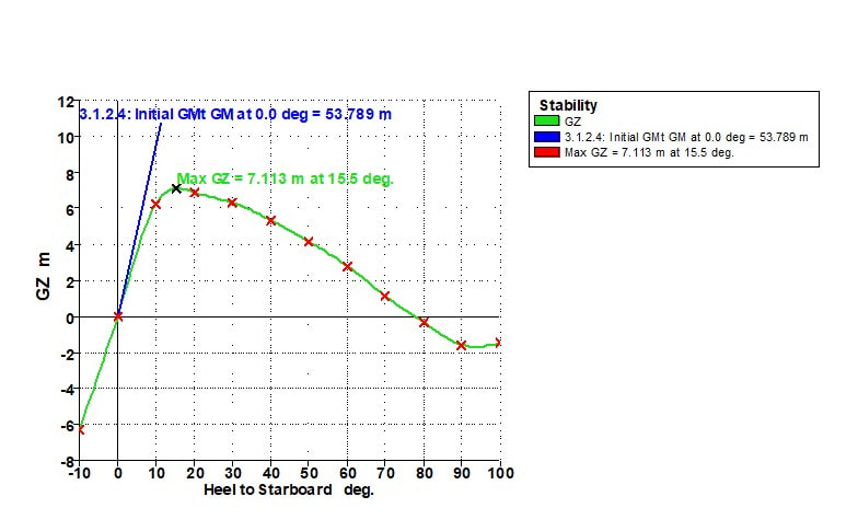
Figure 6: The Statical Stability Curve of Hapi platform
e. Rules and Regulations
HAPI concept has been crossed checked with the existing regulations for similar floating concepts. There are two regulating bodies which are responsible for checking this type of structures – DNV GL (Det Norske Veritas and Germanischer Lloyd) and IMO (International Maritime Organisation). The regulations for floating pontoons/ barge are summarised below [6].
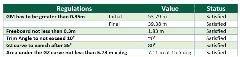
Table 4: Stability Guidelines Check
4. Conclusions
From the calculations above it can be seen that the HAPI concept satisfies all of the regulation criteria. The floating concept for producing clear electricity from wind and current turbines shows that the equilibrium of the floating body has positive stability. Also, the initial metacentric height guarantees for large initial stability.
The results were compared mainly with pontoon shape and general criteria applicable for all ships in order to produce maximum close to the reality result. The criteria provided by the software are limited in this case. Further analysis and consultation is needed with the consultation organisations and classifications bodies before releasing the project.
The results were compared mainly with pontoon shape and general criteria applicable for all ships in order to produce maximum close to the reality result. The criteria provided by the software are limited in this case. Further analysis and consultation is needed with the consultation organisations and classifications bodies before releasing the project.
References
[1] Archimedes, 1897. The works of Archimedes. Cambridge: University Press.
[2] Tupper, E. C., 2013. Introduction to Naval Architecture. Amsterdam: Elsevier, Butterworth Heinemann.
[3] Biran, A. & Lopez-Pulido, R., 2014. Basic Ship Hydrostatics. Ship Hydrostatics and Stability, pp. 23-75.
[4] DNV, 2014. Design of Offshore Wind Turbine Structures DNV-OS-J101, s.l.: Det Norske Veritas AS.
[5] BentleyCommunities, 2018. MAXSURF. [Online]
Available at: https://communities.bentley.com/products/offshore/w/wiki/10688/maxsurf
[6] Maritime New Zeland, 2006. Barge Stability Guidelines, Wellington [N.Z.]: Maritime New Zeland.
|
|
STRATHCLYDE UNIVERITY
16 Richmond Street Glasgow G1 1XQ Scotland, United Kingdom Phone: +44 141 552 4400 https://www.strath.ac.uk © Copyright 2018 |

|