Chosen Location:
|
|
Why HAPI?
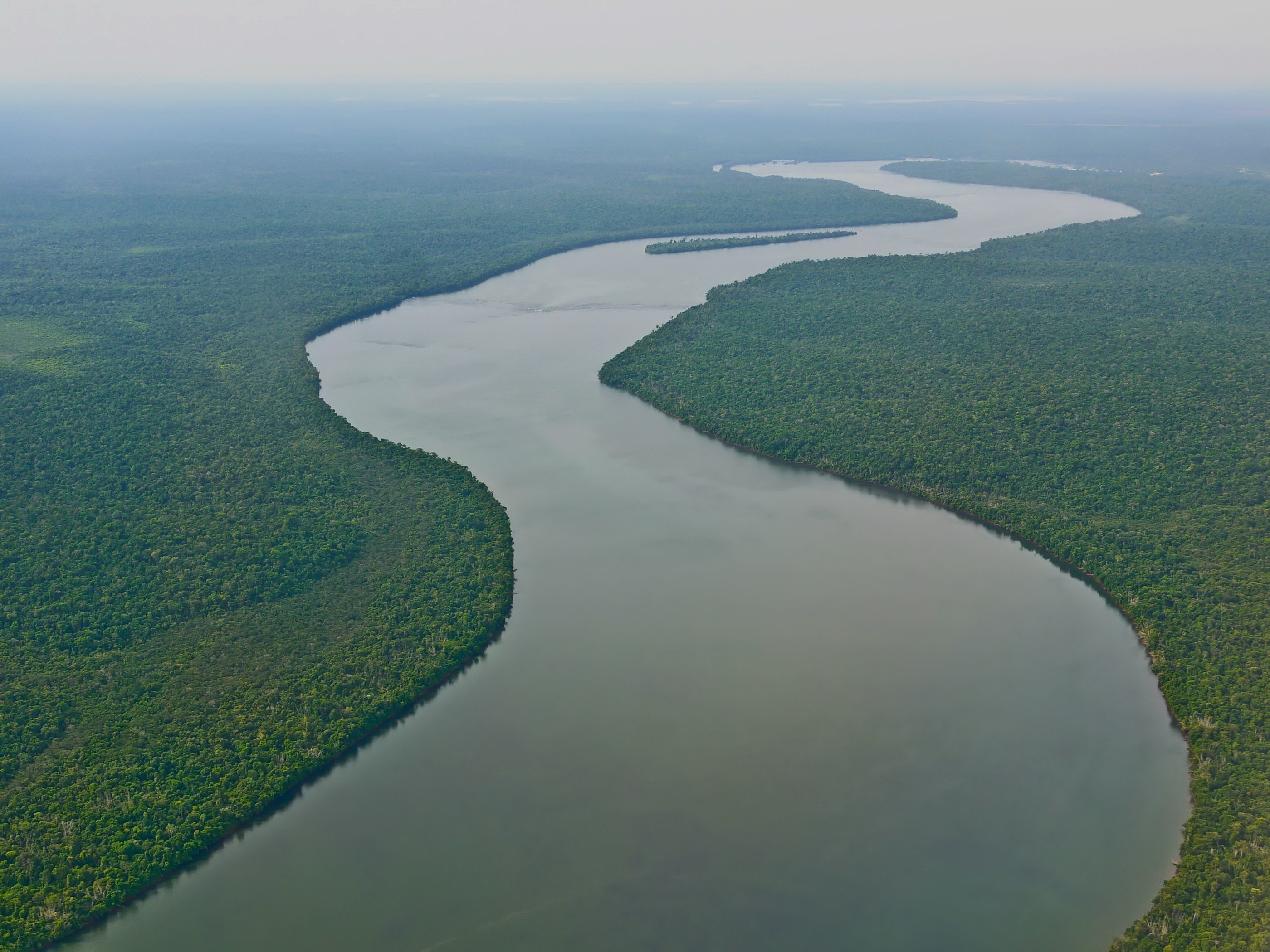
Nile was not only the selected case study but also the inspiration for our project's name. According to Egyptian mythology Hapi was the God of river Nile [1].
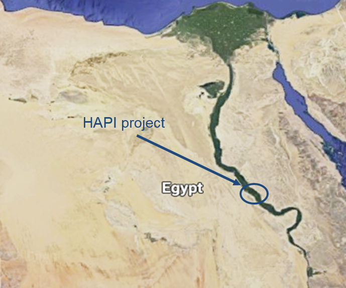
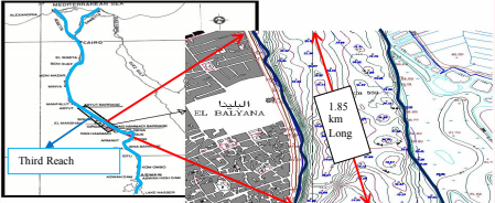
Nile is the longest river in the world and is generally characterized by its tendency to meander; this has led to changes in the value of velocity, water levels, discharge, and bed material varying from one reach to the other [2]. We decided to focus on an area which covers a distance of 185.24 km upstream El-Roda gauge. In order to narrow down our study area we finally selected the part of the Nile that passes through city El Balyana.
|
|
|
Figure 1: River Nile, Egypt, Location of Hapi project
|
Figure 2: El Balyana, the location of Hapi project [4]
|
Morphological factors
|
For the purpose of our project, we had to search river sites that fulfil some basic factors that will be presented below. It is very important for the progress of the project to select a location that better corresponds to our requirements. The first factor that we had to consider was the morphologic characteristics of our river site. We decided to set reference values that would facilitate our choice:
Considering the fact that the deepest points of the river are located in the central channel, the selected river must be wide enough to accommodate our platform. |
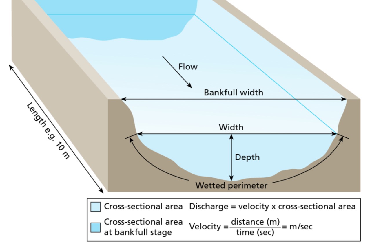
Figure 3: Hydro-graphical characteristics of a river
|
The depth of river Nile changes presents high variability and it is very difficult to find accurate values for a specific part of it. Deposition and erosion takes place every year that affect the river's morphology as it can be seen in Figure 4. It is clear that the deposition was occurred in the East channel at the navigation path as the result of bank erosion that happened at the eastern side [3].
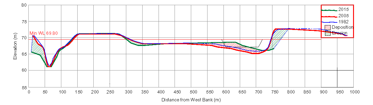
Figure 4: Navigation bottleneck cross section near our selected location [3]
According to [4], it is safe to consider an average of 10 meters as the river depth in a distance of 100 meters from the side banks. Moreover, a distance of 450 meters can be considered as the average width in the selected location. As we can see both values are within the limits of our reference values.
Navigation Channel
|
Using the rivers for navigation has always been a good opportunity for fuel saving and for improving road safety. Especially in the Nile, the cargo transportation plays a significant role in the decrease of the stress on the road network of Egypt. The Egypt Government has decided to work on the navigation development but to do so, it was necessary to modify a navigation channel design within the river course and maintain a navigational depth according to international design, while taking into consideration the stability of the Nile River [3].
|
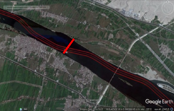
Figure 5: Navigation channel near El Balyana [3]
|
As we can see in the Figure 5, the navigation channel does not always coincide with the central channel of the river. According to the data provided by the Nile Research Institute (NRI), every construction in the river must have a safety distance of 150 meters from the navigation channel. In our case, the width of the river ensures that the legislation, as well as the local fish-farming activities, will not be violated at any case.
Adequate conditions
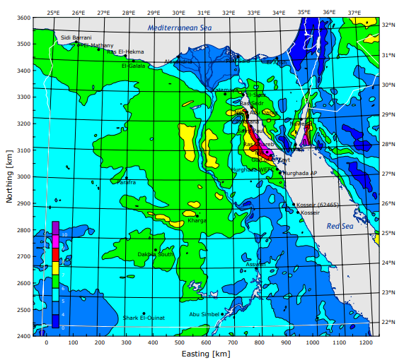
Figure 6: Wind atlas for Egypt [6]
|
Generally, several issues are of concern with regards to the power production performance on river applications. We need to ensure that the existing conditions in the selected area are favorable to our project.
Stating with the wind profile, it has been already proposed in [5] that the specific area has adequate mean wind speed. A milestone regarding the wind data in Egypt, is the 'Wind Atlas for Egypt' which was published recently by the New and Renewable Energy Authority (NREA) and the Egyptian Meteorological Authority (EMA) in Cairo, in cooperation with Risø National Laboratory [6].The'Wind atlas' provides us with analytical wind data, at a specific anemometer height, in every region across the Nile (Figure 6). As it can be seen in the Energy output, the average wind speed in our location is satisfying. |
|
As far as the river water velocity concerns, apart from the water discharge rate it has been difficult to obtain very analytical data. While we are aware of the maximum and minimum expected water velocity, we do not have solid data regarding its variability throughout the year. However, it is proposed to consider an average speed of 0.8 m/s which is suitable for our turbines' capacity. Moreover, the bathometric plot in figure 7 gives a better understanding of riverbed's geometry as well as the different water stream velocities.
|
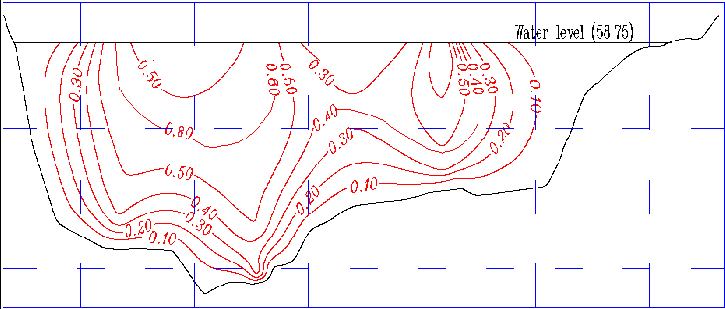
Figure 7: Bathometric data in our location [4]
|
Conclusions
The chosen location has an adequate morphology which ensures that our platform will be accommodated safely. The navigation channel has been taken into consideration and has been carefully checked that legislation will not be violated. Our location offers good conditions in terms of wind speed and water stream velocity and the desired output will be achieved. However, it needs to be mentioned that there have been some locations across Nile with better wind conditions but with smaller stream velocity. Generally it is not easy to find a location where both resources are high.
Once the location was chosen, one big step of the project has been fulfilled. With all the data collected, the next step was to calculate analytically the estimated power output and carefully decide on our platform's geometry.
Once the location was chosen, one big step of the project has been fulfilled. With all the data collected, the next step was to calculate analytically the estimated power output and carefully decide on our platform's geometry.
References
[1] En.wikipedia.org. (2018). Hapi (Nile god). [online] Available at: https://en.wikipedia.org/wiki/Hapi_(Nile_god) [Accessed 28 Jan. 2018].
[2] Fielding, L., Najman, Y., Millar, I., Butterworth, P., Garzanti, E., Vezzoli, G., Barfod, D. and Kneller, B. (2018). The initiation and evolution of the River Nile. Earth and Planetary Science Letters, 489, pp.166-178.
[3] Kamal, N. and Sadek, N. (2017). Evaluating and analyzing navigation efficiency for the River Nile (Case study: Ensa-Naga Hamady reach). Ain Shams Engineering Journal.
[4] Eshra, N. (2014). Study of Application of Small Hydropower for Nile River in Egypt. Middle East Journal of Applied Sciences, (2077-4613), pp.1118-1129.
[5] Ahmed, A. (2011). Analysis of electrical power form the wind farm sitting on the Nile River of Aswan, Egypt. Renewable and Sustainable Energy Reviews, 15(3), pp.1637-1645.
[6] Mortensen, N. G., Said Said, U., & Badger, J. (2006). Wind Atlas for Egypt. In Proceedings of the Third Middle East-North Africa Renewable Energy Conference (on CD-ROM) References
|
|
STRATHCLYDE UNIVERITY
16 Richmond Street Glasgow G1 1XQ Scotland, United Kingdom Phone: +44 141 552 4400 https://www.strath.ac.uk © Copyright 2018 |

|