
 Home
Home 

Introduction
Technology incorporating an oscillating hydrofoil varies considerably from more commonly used rotational MEC devices. The oscillating hydrofoil induces hydrodynamic lift and drag forces due to a pressure difference on the foil section caused by the relative motion of the tidal current over the foil section. These forces induce a resultant tangential force to the fixing arm which by driving reciprocating hydraulic rams pump, high pressure hydraulic fluid to turn a hydraulic motor and electrical generator. This section will highlight the principles of operation, the degree of complexity in optimising the device, the mathematical model developed; draw some conclusions and consequent recommendations.
Engineering Business Ltd., in conjunction with funding from the
DTI, developed the “Stingray” oscillating hydrofoil
as a developmental prototype to prove the robustness of the concept,
the design and technology and the economical feasibility. As it
stands the inflated development costs of this device in the current
economic climate is prohibitive and has caused the project to
be suspended. The lessons that were learned from the development
and testing of the full scale 150kW prototype and have been implemented
in a large scale second generation model to be developed and tested
at a later date.
The model outlined by the developemtnal nature
of the device has similar principles of operation to that of "Stingray"
however our model is generic in nature and hence no direct comparison
relating "Stingray's" performance should be extrapolated.
Principals of operation
The main principal of operation as introduced
above is relatively quite simple. Given a positive or negative
angle of attack relative to the tidal stream in-flow, the hydrofoil
will rise and fall in an oscillating motion. The rate at which
this cycle occurs is interdependent on a considerable number of
hydrodynamic and mechanical variables.
The lift which drives the device is dependant on the flow velocity
and density, the foil surface area and aspect ratio and the foil
profile characteristics, namely it’s lift and drag coefficients
for an optimum angle of attack.
For further explanation of hydrofoil dynamics
please see hydrodynamics section
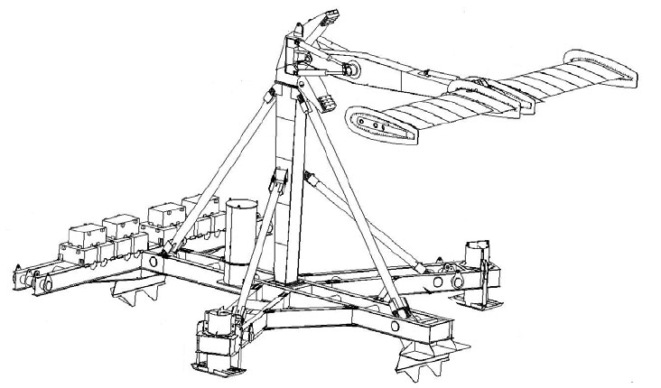
Figure 1 Stingray Assembly © Engineering Business Ltd 2005
Unlike conventional rotational technologies which once operational generate, at constant rotational speed, the lift acting on the oscillating hydrofoil approximates a sinusoidal decay from the horizontal to vertical arm positions. This non linear velocity and loss in momentum cause the device to inherently have a large degree of mechanical complexity in developing and optimising the devices power output.
As the lift decays sinusoidaly, the degree of oscillation has
to be limited (approx 35°) to prevent significant loss of
lift. The maximum lift is governed by empirical optimum angle
of attack. This angle of attack is relative to the inflow velocity,
and as the hydrofoil is continually in motion through the inflow,
this angle of attack must be controlled and dynamically optimised
to maintain efficient performance.
This is achieved by programme logic control (PLC), which continually
monitors mechanism parameters, the system hydraulic pressure,
the inflow velocity and the arm position. The PLC signal then
controls a hydraulic ram mounted on the oscillating arm to actuate
the hydrofoil angle of attack. Holding the hydrofoil stably at
its optimum angle of attack is critical, if the foil tends to
wobble it significantly reduces lift, increases drag and decreases
the overall cycle time.
Furthermore this same system is used to overcome the pitching
moment on the hydrofoil, stop its motion and return the cycle
in the opposite direction. This characteristic is the single most
limiting factor of the device. In changing the direction of oscillation,
up to 15% of the device power rating is spent in firing hydraulic
pressure accumulators to rapidly change the angle of attack. Similarly
if this accumulation pressure is reduced, the cycle time decreases
and the overall power output is decreased.
Lastly monitoring & optimisation of power extraction is also
required. As the lift and angular velocity is sinusoidal in nature
so is the resultant power curve.
Power take-off from the cycle however is not constant and neither
sinusoidal. Power extraction cyclically occurs only after the
arm’s angular velocity has reached a rated cut in speed
to allow the device to build up speed and power.
Modelling
The modelling undertaken and outlined below, is generic in comparison with the discussion above, as the requirements of this project is to indicate the power output and power coefficient for a given flow velocity and device size.
A NACA 0015 symmetrical, high lift, low drag foil profile was chosen to be the basis of the hydrofoil characteristics. The foil is symmetrical, and hence operates for positive and negative angles of attack. The hydrodynamic properties of the profile have been tested and are well documented. Foil endplates prevent the propagation of wingtip vortices and consequent loss of lift and induced drag and enables simplified analysis.
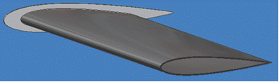
Figure 2 NACA 0015 Section Profile
The lift and drag coefficients which are arrived at empirically
are illustrated below for varying angle off attack. The optimum
angle of attack can be seen to be at 12°. Larger angles of
attack will induce drag and the device will stall, reducing lift,
and power output.
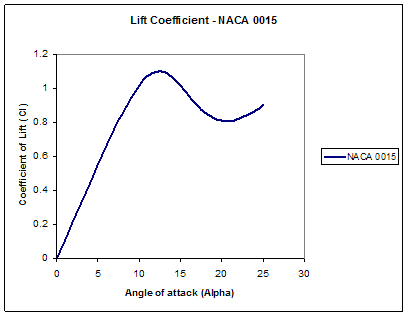
Figure 3 Coefficient of Lift
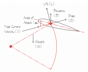
Figure 4 System Forces
Assuming that the hydrofoil angle of attack (a) is maintained
at a constant the resultant lift generated can be calculated by;
![]()
Equation 1 Lift Equation
Where ![]() is water density,
is water density,![]() is bulk flow velocity, S is foil planer area and CL
is the lift coefficient.
is bulk flow velocity, S is foil planer area and CL
is the lift coefficient.
Similarly the Drag experienced is calculated using;
![]()
Equation 2 Drag Equation
Where CD is the drag coefficient.
Further assuming that the buoyancy forces from the GRP hydrofoil
balances the weight from the steel arm structure to prevent cyclic
loading on the device, the system forces are resolved into tangential
and normal forces to the direction of oscillation.
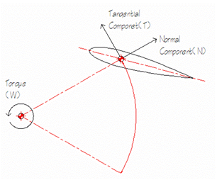
Equation 3 Resolved System Forces
The tangential force T for a given angle of oscillation ß is given by;
![]()
Equation 4 Resultant Tangential Force
It should be noted that the drag experienced on the foil, can
have positive effects depending on the phase of the cycle. Further
more induced drag and stall at extreme angles of rotation can
be used to accelerate change in oscillation direction and decrease
the cycle time.
The torque applied around the centre of rotation is dependant
on the arm length or the radius of rotation. However, the longer
the arm, the more it weighs disturbing the buoyancy-weight balance
of the arm-foil assembly. Further it will affect the system inertia
and the cycle time accordingly.
The instantaneous torque experienced is a product of the resultant
Tangential force above by the Arm length.
![]()
Equation 5 Instantaneous Torque
The cyclic torque is resolved by calculating the
resultant tangential forces through the cycle angle of rotation
from ßmin to ßmax.
The output power cycle can then be calculated for a specified
cycle time Ct.
Equation 6 Instantaneous Power
Where w (omega) is the angular velocity in radians per second,
and phi is the cycle phase angle.
Again the cyclic power can be evaluated over the cycle and a root
mean square gives the associated cycle power.
Fig. 7 shows the resultant power curve for a model with a 2m/s flow velocity, a hydrofoil area of 45m2, arm length of 10.9metres and operates with a power coefficient (CP) of 0.12.
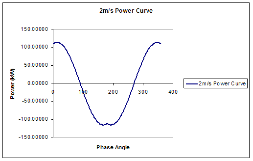
Figure 7 Model Resultant Power Curve

back to top
Conclusions
It is apparent that the oscillating hydrofoil
has a large degree of complexity with many system variables. This
complexity requires continuous monitoring to operate the device
at a considerable loss of power to the hydraulic actuation system.
The device operates at a low coefficient of power. Optimisation
of the control system governing angle of attack is needed to decrease
cycle time, increasing the power output.
Simplification of the design to maintain system momentum in a
rotational setup may reduce the power lost in actuating the foil
angle of attack and minimise hydraulic pressure losses and hence
increase output power. This could also be achieved by operating
3 foils out of phase with their respective hydraulic systems linked.
This would automatically provide a continuous high pressure reserve
to actuate each of the alternate foils and also minimise resultant
lift from the seabed reducing mooring requirements & costs.
A full set of results is available in the results download package here.
References
| 1 | DTI, The Engineering Business: Research and Development of a 150kw Tidal Stream Generator - Phase 1 [ETSU T/06/00211/00/REP; URN No 02/1400]. [PDF] 2002 [cited 02 May 2006]; Available from http://www.dti.gov.uk/renewables/publications/pdfs/T00211.pdf |
| 2 | DTI, The Engineering Business: Research and Development of a 150kw Tidal Stream Generator - Phase 2 [ETSU T/06/00211/00/REP; URN No 02/1400]. [PDF] 2003 [cited 02 May 2006]; Available from http://www.dti.gov.uk/renewables/publications/pdfs/T00211.pdf |
| 3 | DTI, The Engineering Business: Stingray Tidal Stream Energy Device Phase 3 [ETSU T/06/00230/00/00; URN No 05/864]. [PDF] 2005 [cited 02 May 2006]; Available from http://www.dti.gov.uk/renewables/publications/pdfs/T00211.pdf |
| 4 | SHIVERS, J. and CARPENTER, P., NACA TN-4356: Effects of Compressibility on Rotor Hovering Performance and Synthesized Blade-Section Characteristics Derived from Measured Rotor Performance of Blades Having Naca 0015 Airfoil Tip Sections, 1958 NASA Langley |
| 5 | MUNSEN, B., et al., Fundamentals of Fluid Mechanics. 3 ed. 1998, New York: John Wiliey & Sons. pp. 877. ISBN |
Go back to Contents