
 Home
Home 
| Turbine
Theory |
Intro
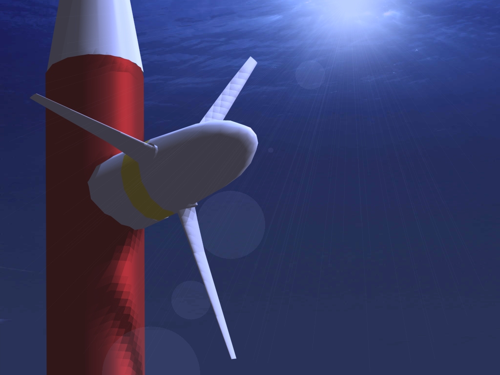
Perhaps the most obvious type of device, the horizontal axis
marine current turbin (HAMCT) shares almost all it’s attributes
with the more familiar wind turbine. The principle of operation
is identical and is energy conversion is performed in a similarily
elegant manner. Only the massively increased energy density of
water and the possibility of cavitation, coupled with the destructive
wear and tear of a submerged structure result in any change in
design with the consequence that HAMCTs are stockier and stubbier
than wind turbines.
Like it’s wind power counterpart, the horizontal turbine
must be yawed into the flow although in the case of bidirectional
tidal stream flow, it is sufficient to collectively pitch the
blades according to flow direction and operate the turbine in
both up and downflow conditions.
Principle of operation: resultant hydrodynamic forces from inflow (largely) perpendicular to the rotor has components acting in the plane of the rotor, normal to the axis of the blade. The resulting torque is transferred via a shaft and gearbox to an alternator.
Modelling: Blade element momentum theory is applied to a generic model to calculate shaft power and rotor thrust. This approach is computationally quick, gives accurate results, and may be automated for various flow speeds, rotational speeds and rotor geometries.
back to top
The Horizontal Axis MCT Model
Due to the previously mentioned non-availability of information, the model has had to be generated in the most generic sense. This does not preclude similarity with existing commercial devices, as mentioned, although for reasons to be covered, the physical characteristics of our turbines most closely resemble those used by Bahaj et al.
The primary concern is structure. Common sense dictates that an MCT will closely resemble a wind turbine, while a consideration of the massively increased loading indicates that such turbines will be more compact in order that the structure should be less massive. This applies to blades mainly, and the result is one where a massively thick aerofoil section is required at the root, and the thickness throughout remains relatively higher than that of a wind turbine.
Secondary is cavitation. If, as described in the hydrodynamics section the local cp drop below a critical value, cavitation will occur in the region of low pressure on the hydrodynamic top of the blade. As discussed, the results are initially a drop in performance, and in the long term a reduction in the integrity of the blade surface. As tendency to cavitate depends on (primarily) on local dynamic pressure, and hence the square of the local (relative) velocity, it is likely that cavitation will initially occur at the blade tip. Since an aerofoil’s cp is largely dependant on angle of attack it is apparent that to avoid cavitation, twist at the blade tip and blade tip velocity must be considered.
A tertiary consideration is aerofoil section, and this depends on the first two considerations. As long as the aerofoil is suitably thick enough to accommodate the required structure, whilst being chosen to reduce the likelihood of cavitation, the section itself is not of primary importance (within reason).
Within these bounds, it is desirable that the blade develops as much torque as possible and it is found that the relatively low tangential velocity at root requires a large amount of twist for optimal angle of attack to the resultant velocity, and a relatively large chord to accommodate the thick aerofoil and to increase tangential thrust. Towards the tip it is desired that lift should drop off and the reason for this is twofold: the first is structural considerations, and the second is the dependence on lift generation of an aerofoil with local dynamic pressure. The result is a blade tangential thrust distribution that is almost elliptical. Elliptical distribution would be optimal, but would lead to the following blade design, and obviously is non-realisable:
As a result of this consideration, our model is as follows (for actual values see HAMCT program available for download here):
• Non-linear variation in aerofoil thickness
• Non-linear twist distribution
• Linear chord length variation along blade
• Hub cutout considered as being 1/5 of the radius
• Aerofoils are all symmetric NACA four-digit sections –
ease of scaling for thickness, ease of locating section characteristics
• Variable pitch blades
The precise geometry has been compared to that of Bahaj in order to assure that it is sensible.
The blade element momentum program is then input with the geometry of the device, and a suitable lookup table for aerofoil characteristics at the appropriate Reynolds number range is provided. A module is added to the program that calculates the local cp at the blade tip and provides indication of likely cavitation. Finally, the model is run for a series of freestream velocities and RPMs, and within the cavitation bounds the optimum RPM and pitch setting for the blades is computed at each velocity.
This calculation has been performed in similar conditions to the experiments of Bahaj et al, and the results for this validation case follow. The tolerance for convergence of induction factors is set at 1x10⁻³ as a compromise between accuracy and computational time, and gives an average convergence time 0.0016 seconds per blade element (on an uninspiring desktop PC). The number of blade elements is simply calculated as if each blade element was spaced 1mm from it’s neighbours, and they are infinitesimally thin.
The model is now reconfigured so as to run calculations between 0.5 and 7ms-1, considered the maximum range of realistically expectable flow speeds. The radius is increased in .5 metre increments from a radius of 2.5m to a radius of 20m, which is considered the absolute maximum for West of Scotland conditions. The rotational speeds are incremented in revolutions per minute from a minimum of 1 RPM up until the integer immediately above that at which cavitation is likely to begin. This does result in some farcically low rotational speeds at the larger end of the radius range, but does yield a suitable number of results for various flow conditions. The blade collective pitch setting is also altered from -5 to 20 degrees. The output screen from the program run for a radius of 10m is displayed below.
Thus, assuming the turbine is to be run at CPmax in
all flow conditions, the following results have been obtained.
They are fairly self explanatory, but will be discussed in more
detail within the methodology sections.
Results from the model may be downloaded in PDF format from the results download package here.
Go back to Contents