
This section of the website looks at the theory behind the distribution network necessary for any district heating scheme. The two sub menus in this section describe the methods used to calculate the heat losses in the pipes and the general piping theory.
The hot water heated in the electrode boiler and stored in the thermal storage will be delivered to the individual buildings using a network of piping. The piping will consist of a supply and return line with various pipe diameters and fittings. It is advantageous to design the network to return the water with as low a temperature as possible. The diagram below shows the general working process used to calculate the key elements throughout the distribution network.
GENERAL CALCULATION PROCESS
When sizing the pipes it is important to find the peak-heating load required to heat the buildings included into the district-heating network. Once a peak-heating load is established it is possible to calculate the required diameter of the supply and return. Each pipe must be capable of carrying the heating load of all the buildings that it connects to. Consequently, any pipes branching off to serve a individual house will be thinner than those carrying the entire heating load.
It is also important to consider future expansion when sizing the pipes that will carry the hot water. A narrow pipe will restrict the network to a particular heating load. The calculation process used to size the supply and return pipes for the two scenarios is seen in the diagram below.
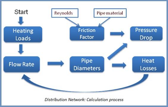
Once the peak heating demand is established the supply and return pipes can be sized. The diameters of the pipes are calculated based on required mass flow rate to each building. Additionally, the heat losses and pressure drops can be determined using the following iterative calculation process:
- 1. From the peak heating load a mass flow rate for each section of piping can be found.
- 2. From this the pipe diameters are found.
- 3. Then, the heat losses can be calculated and added back into the peak heating load require of each pipe section.
- 4. The pressure drop through each section of piping can also be calculated from the pipe specifications and the flow characteristics
PIPE DIAMETER SIZING
However, it is important to remember that the exact pipe diameters that are calculated may not be available. Consequently, a pipe size must be chosen for each stretch of piping in a size that is available. Typically, pre-insulated steel pipes come with internal diameters of 25mm, 50mm, 65mm, 80mm, 100mm and so on.
PRESSURE DROP
Another important consideration is the pressure drop within the piping network. This is essential when sizing the variable speed pumps that will be required within the system. The pressure drop selected would be the largest over a continuous run of piping. This value is a function of the friction factor which is found using the reynolds number and the pipes relative roughness as seen in the calculation process above.
However, there is also a pressure drop associated with many of the pipe fittings found within a typically district heating network. In order to include the pressure drop associated with bends in the pipework and any pipe fittings (such as mixing and diversion valves) an equivalent length is added to the total pipe length within the calculation process.
FURTHER DETAILS
Further detailed information on the heat loss in the piping network and other key considerations such as the piping material and the difficulties associated with laying the pipes can be found within the following links: