Individual Components
Electrolyser The electrolyser uses electricity to split water into hydrogen and oxygen. The hydrogen is collected, compressed and fed into a storage tank.

Fig 1 - Electrolysis phenomenon
Source: http://www.nature.com/ncomms/journal/v1/n8/full/ncomms1112.html There are several types of high performance electrolysers. Alkaline electrolysers are the more mature technology [6]; with Proton Exchange Membrane (PEM) electrolysers offering potentially high performance [7]. Other types, which operate at high temperatures, are out of scope for this project.
Compressor
A compressor is used in the system to compress the hydrogen to a smaller volume, and so reduce the necessary volume of the hydrogen storage tank. For this system, a storage pressure of 200 bar has been selected.
Compressors are quite expensive, this is why it have a large impart on the feasibility of the system. Figure 3 below is an example of the desired compressors that range from £40,000 - £200,000 [8]. 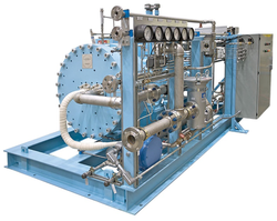
Fig 2 - Example of a compressor
Source : http://oilgasequipment.en.china-ogpe.com/html/product_Hydrogen_Compressor_3_29594.html Hydrogen storage tank
A significant volume of hydrogen must be stored, to provide the immediate fuel source for this peak power plant when it is required to generate electricity. To reduce the storage volume, the hydrogen will be stored at a pressure of 200 bar. The tank will need to be suitably designed, probably double-skinned, to prevent leakage of hydrogen.

Fig 3 - Example of storage tank suitable for our module
Source : https://forums.teslamotors.com/forum/forums/hydrogen-viability-right-around-corner-really Fuel cell
A hydrogen fuel cells converts the chemical energy in hydrogen to electricity, with heat and water as the only by-products. A single fuel cell consists of two electrodes, a cathode and an anode sandwiched together with electrolyte in between [9, 10].

Fig 4 - Individual fuel cell principle
Source : http://energystoragesense.com/fuel-cells-and-hydrogen/ Comparison of fuel cell technologies
There are several types of fuel cell available. For this project, equipment is selected which operates at ambient temperature, for simplicity. It is most likely that a PEM type fuel cell would be used. Properties of some other types of fuel cell are tabulated below. 
Adapted from Argonne National Laboratory, cited by U.S. Department of Energy Hydrogen Programme, 2006 [11], and Spiegel, 2007 [12]
The size of system components are determined at a later stage in the project. However, the size of the fuel cell can be estimated from its required output capacity of 3MW of electricity (to meet STOR requirements). An estimate is made here from a commercially available Hydrogenics 1 MW hydrogen PEM fuel cell [13].

Fig 5 - Fuel cells
Source : http://www.hydrogenics.com/images/default-source/default-album/acor3600-2-web.jpg?sfvrsn=2 According to the manufacturer’s information, the plant measures 8ft by 10ft by 50ft (or 2.4m by 3.0m by 15.2m).

Fig 6 - Fuel cells
Source: http://www.hydrogenics.com/images/default-source/default-album/kolong---1mw-plant.jpg?sfvrsn=2 To produce 3MW of electricity, 3 such plants would be needed, occupying a volume of just over 330 cubic metres. There may be some space savings in locating 3 plants together, for example some auxiliary components may be able to be shared. Furthermore, if more efficient plants are developed in the future, they be expected to would occupy smaller space. The efficiency of this Hydrogenics plant is quoted as being 49% (LHV), which equates to 41% HHV, the measure used throughout this webpage. [1] A. Godula-Jopek, Introduction. In: "Hydrogen production by electrolysis" ed. A. Godula-Jopek. Weinheim, Germany: Wiley-VCH, 2014.
[2] A. Godula-Jopek, Hydrogen storage options including constraints and challenges. In: "Hydrogen production by electrolysis", ed. A. Godula-Jopek. Weinheim, Germany: Wiley - VCH, 2014. [3] National Grid. (2013). Short Term Operating reserve (STOR) Frequently asked questions. Available: http://www2.nationalgrid.com/uk/services/balancing-services/reserve-services/short-term-operating-reserve/ [4] National Grid. (2016). Short Term Operating Reserve (STOR) Annual Market Report 2014/2015. Available: http://www2.nationalgrid.com/UK/Services/Balancing-services/Reserve-services/Short-Term-Operating-Reserve/Short-Term-Operating-Reserve-Information/ [5] US Department of Energy, Energy Efficiency & Renewable Energy, and Fuel Cell Technologies Programme. (2010). Fuel Cells. Available: https://www1.eere.energy.gov/hydrogenandfuelcells/pdfs/fct_h2_fuelcell_factsheet.pdf [6] in Energy Efficiency & Renewable Energy, ed, 2010. [7] P. Millet, PEM water electrolysis. In: "Hydrogen production by electrolysis" ed. Godula-Jopek, A. Weinheim, Germany: Wiley, VCH, 2015. [8] Pure Energy Centre. (2016). Hydrogen compressors. Available: http://pureenergycentre.com/hydrogen-compressor/ [9] US Department of Energy, Energy Efficiency & Renewable Energy, and Fuel Cell Technologies Programme. (2010). Fuel Cells. Available: https://www1.eere.energy.gov/hydrogenandfuelcells/pdfs/fct_h2_fuelcell_factsheet.pdf [11] U.S. Department of Energy Hydrogen Programme. (2006). Hydrogen fuel cells. Available: https://www.hydrogen.energy.gov/pdfs/doe_fuelcell_factsheet.pdf [12] C. Spiegel, Designing and building fuel cells. New York: McGraw-Hill, 2007. [13] Hydrogenics. (2013). Fuel cell megawatt power generation platform. Available: http://www.hydrogenics.com/hydrogen-products-solutions/fuel-cell-power-systems/stationary-stand-by-power/fuel-cell-megawatt-power-generation-platform |
H3P PROJECT - Modular Peak Power Plant
