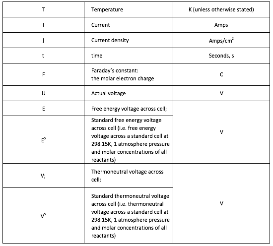
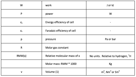
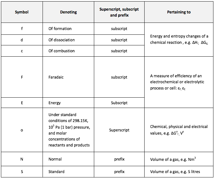
H3P PROJECT - Modular Peak Power Plant
  • Home
  • Context
  • Project
    • Project Introduction >
      • Background
      • Concept & Definition
      • Individual components
    • Theory >
      • Electrochemistry
      • System Losses
      • Assumptions & Symbols
    • Fuel Cell Measurements
  • Model
    • Approach
    • Parameters Definition
    • MATLAB Model
  • Results & Conclusions
    • H3P - Results
    • Discussion
    • Conclusions
  • Additional Information
    • Further Developments
    • Other Considerations
    • Alternative Applications
    • Acknowledgments
    • Bibliography
  • Team

Project - THEORY

Assumptions

  • Financial assumptions
  1. The annual operating and running costs of the plant will be 2% of its capital cost.  The capital cost was based on the estimated actual purchase price of equipment.
  2. Standard financial parameters of an interest rate of 8%p.a. and a loan repayment period of 12 years were used throughout.  These can easily be changed if desired.


  • System assumptions
  1. The system consists only of the main components listed.  In reality, additional auxiliary components will be needed.


  •  Electrolyser and fuel cell assumptions
  1. Temperature of the electrochemical reactions i.e. electrolyser and fuel cell, is always 25oC, 298.15K.  (Probably not accurate, but likely changes (e.g. to around 50oC) have a very minor effect on calculated results.)
  2. Water is always liquid.  Hydrogen and oxygen are always gaseous and behave as ideal gases.
  3.  At the electrolyser, the partial pressure of hydrogen and oxygen at the respective electrodes will be 1, and the total pressure is 1 atmosphere.
  4. Around the fuel cell, the partial pressure of oxygen will remain at 21% throughout operation.  (Some depletion in oxygen may occur if the equipment is not very well ventilated.)  The partial pressure of hydrogen at the anode is 1 atmosphere.
  5. In acid systems the molar concentration of hydrogen ions is molar, and in alkaline systems, the concentration of hydroxide ions is molar.  These concentrations will not change during operation.  (This assumption is an approximation, however it is assumed valid to expect effort to be made to maintain stable operating conditions at whatever chosen concentration.)
  6. The operating pressures of both electrolyser and fuel cell are 1 atmosphere.  (In practice, electrolysers and fuel cells can operate between atmospheric pressure and a few tens of bar.  There are modest efficiency savings to be had in operating at higher pressures.  However, for simplicity, the system selected does not operate at pressure.)


  •  Compressor assumptions
  1. Compression of the hydrogen will be to 200 bar.
  2. Compression will be isothermal.  This will be an aim, but is not likely to be strictly true.   A more detailed calculation would allow for some heating of the hydrogen.

Symbols

  • Table 1: Symbols
Picture
Picture
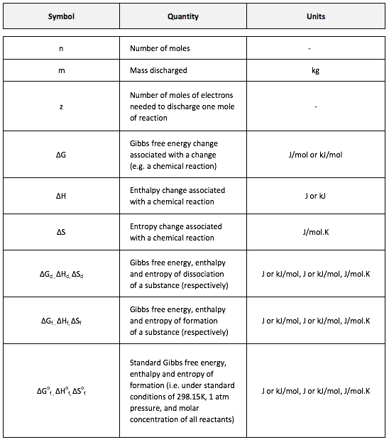
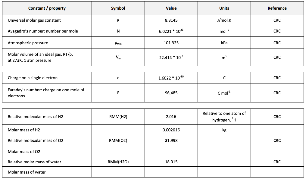
[1] The volume of a gas is often stated in “Normal metres cubed, Nm3”, which is the volume the gas would occupy at 273.15K and 1 atmosphere pressure, or “Standard metres cubed, Sm3” which is the volume the gas would occupy at 288.15K and 1 atmosphere pressure. 
Picture

  • Table 2: State of matter
Picture


  • Table 3: Subscripts, superscripts and prefixes

  • Table 4: Physical and chemical constants
Picture
Picture

  • Table 5: Conversion charts
Picture
Picture
Picture
Picture
Create a free web site with Weebly