
heating control schemes
System design
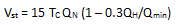
A complementary thermal store is necessary to absorb excess heat from the biomass boiler during times of low load demand, and release it when there is a temporal deficit from conventionally non-despatchable solar thermal heating contributions. A thermal store should be designed specific to the quantity of expected generation from renewable heat, ensuring sufficient capacity to absorb all excess heat, while also independently meeting the combined space heating and hot water demand for a relevant domestic property over a period of potentially several days. As a consequence, the optimal sizing of thermal stores has been the subject of detailed research, outputting some relevant guidelines. European Standard EN 303-5 contains the following formula to calculate the size of storage tank required for a batch fed boiler within a stove:
A complementary thermal store is necessary to absorb excess heat from the biomass boiler during times of low load demand, and release it when there is a temporal deficit from conventionally non-despatchable solar thermal heating contributions. A thermal store should be designed specific to the quantity of expected generation from renewable heat, ensuring sufficient capacity to absorb all excess heat, while also independently meeting the combined space heating and hot water demand for a relevant domestic property over a period of potentially several days. As a consequence, the optimal sizing of thermal stores has been the subject of detailed research, outputting some relevant guidelines. European Standard EN 303-5 contains the following formula to calculate the size of storage tank required for a batch fed boiler within a stove:
Where:
Domestic hot water and solar panel options
Several manufacturers design thermal storage tanks with additional internal coils for specific solar thermal contributions to domestic hot water supply, where mains “unheated” water is introduced at the bottom of the upper coil and funnelled through a heating process to instantaneously satisfy demand whenever a tap is opened. The input solar coils are specifically positioned lower down within the tank to maintain a minimal temperature gradient within the storage tank, and speed up the internal heating process during times of high solar thermal contribution.
- V_st is the volume of the store
- T_C is the combustion time at rated heat output
- Q_N is the nominal heat output
- Q_H is the building heat load
- Q_min is the minimum output of the boiler
Domestic hot water and solar panel options
Several manufacturers design thermal storage tanks with additional internal coils for specific solar thermal contributions to domestic hot water supply, where mains “unheated” water is introduced at the bottom of the upper coil and funnelled through a heating process to instantaneously satisfy demand whenever a tap is opened. The input solar coils are specifically positioned lower down within the tank to maintain a minimal temperature gradient within the storage tank, and speed up the internal heating process during times of high solar thermal contribution.
Boiler control systems
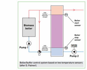
The simple control system commonly implemented in biomass boiler configurations operated with two thermostatically deterministic sensors. Placed at the top and bottom of the thermal storage tank, they provide approximate representation of system inlet and outlet temperatures. In an assumed autonomous ignition system, the biomass boiler (our inlet) ceases combustion when the hot water interface has reached the bottom sensor during charging (T2), and re-commences when the intermediary buffer vessel has discharged to the level of the upper sensor (T1). The primary problem within such a simplistic control arrangement is that at daily start-up (one of the two conventionally prominent peaks in domestic load demand) the buffer vessel emptied fully before biomass boiler ignition, and the load demand must be supplemented for a short period of time by an auxiliary boiler or whatever form of relevant backup generation is available while the biomass boiler warms up (boiler dependent, this heat-up phase can take an hour or more). Using a comparatively larger buffer vessel solves this problem.
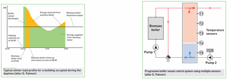
The figure below shows a typical winter load profile for a reference building occupied between 08:00 and 18:00 with a biomass system operation representative of common pattern and a buffer vessel superimposed. The biomass boiler is sized at 50% of the peak load on the winter design day (i.e. the outdoor design temperature) with a buffer vessel capacity ratio of 34 l/kW at a buffer vessel temperature differential of 25 °C. When the heat demand initiates at approximately 06:00, pump 2 will switch on and begin to discharge the buffer vessel. The biomass boiler is thermostatically controlled to ignite once the buffer vessel has fully discharged (the cold interface having reached the upper temperature sensor). While the biomass boiler is heating up, examined over one hour increments, the auxiliary boiler has to satisfy any deficit. When the biomass boiler eventually comes on-line the load is shared between the biomass and auxiliary boilers to operate at optimum efficiency. In the example provided, 85% of the energy is being provided by the biomass boiler.
The simple control system commonly implemented in biomass boiler configurations operated with two thermostatically deterministic sensors. Placed at the top and bottom of the thermal storage tank, they provide approximate representation of system inlet and outlet temperatures. In an assumed autonomous ignition system, the biomass boiler (our inlet) ceases combustion when the hot water interface has reached the bottom sensor during charging (T2), and re-commences when the intermediary buffer vessel has discharged to the level of the upper sensor (T1). The primary problem within such a simplistic control arrangement is that at daily start-up (one of the two conventionally prominent peaks in domestic load demand) the buffer vessel emptied fully before biomass boiler ignition, and the load demand must be supplemented for a short period of time by an auxiliary boiler or whatever form of relevant backup generation is available while the biomass boiler warms up (boiler dependent, this heat-up phase can take an hour or more). Using a comparatively larger buffer vessel solves this problem.
The figure below shows a typical winter load profile for a reference building occupied between 08:00 and 18:00 with a biomass system operation representative of common pattern and a buffer vessel superimposed. The biomass boiler is sized at 50% of the peak load on the winter design day (i.e. the outdoor design temperature) with a buffer vessel capacity ratio of 34 l/kW at a buffer vessel temperature differential of 25 °C. When the heat demand initiates at approximately 06:00, pump 2 will switch on and begin to discharge the buffer vessel. The biomass boiler is thermostatically controlled to ignite once the buffer vessel has fully discharged (the cold interface having reached the upper temperature sensor). While the biomass boiler is heating up, examined over one hour increments, the auxiliary boiler has to satisfy any deficit. When the biomass boiler eventually comes on-line the load is shared between the biomass and auxiliary boilers to operate at optimum efficiency. In the example provided, 85% of the energy is being provided by the biomass boiler.
references
[1] Biomass Heating: A guide to small log and Wood pellet systems, Crown copyright (2011).
[2] Biomass Heating: A guide to medium scale log chip and pellet systems, Crown copyright (2011).
[2] Biomass Heating: A guide to medium scale log chip and pellet systems, Crown copyright (2011).