
conceptual control scheme
The conceptual control scheme we are able to present follows a very simple logic gate procedure, checking heat energy available in the thermal store against upcoming occupancy demand, and then proceeding through a series of logic gates featuring renewable forecasting capacities to only utilise biomass fuel as a last resort measure. As this conceptual control scheme was designed specifically to our case study of Findhorn Ecovillage, it incorporates branches to facilitate the alternative use of electric immersion heaters during times of high onsite wind generation where the short, intermittent firing of the biomass boiler would not be technically justifiable (assuming absent solar thermal contributions). Although there is additional provision for electric immersion heaters, their use would appear to compromise our motivations of seeking more prosperous environmental sustainability. Its operation has therefore been restricted to meet only an urgent, unpredictable hot water demand and, as described above, where the energy deficit between demand and renewable supply is not sufficient to justify periodic firing of the biomass boiler.
This introduces the conceptual control schemes specific flow hierarchy:
1. Individual store (buffer vessel)
> 2. Central thermal store
>> 3. Solar thermal forecast
>>> 4. Biomass operation
>>>> 5. Electric immersion
Our conceptual control scheme is now presented in Figure 1. Please note that due to its level of intricacy it is difficult to provide a clear, presentable format and the user may have to extract the figure into appropriate software with zoom capability. Also note that for purposes of clarity, to distinguish between the individual houses thermal stores and the main boiler room thermal store, the individual store in Figure 1 is referred to as the “buffer vessel”.

Figure 1. Conceptual control scheme.
We prove some very basic example simulations in for reference in Table 2 below below using relevant data provided in Table 1:
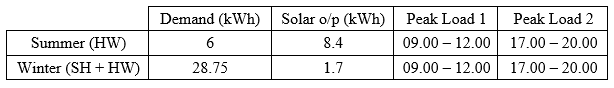
Table 1. Summer and winter demand vs daily solar thermal output.
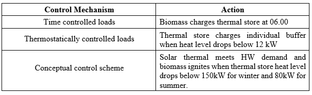
Table 2. Consequent example actions of various control mechanisms
To give a brief explanation of the content formulating these tables, summer demand was calculated based solely on hot water demand where a good solar thermal forecasting capacity within the control scheme may integrate with some preliminary level of demand side management to ensure all loads are satisfied through solar thermal contributions.As the solar contributions are not sufficient to meet the winter demand, heat from the individual store (or buffer vessel) and central thermal store are always required. Timer and thermostat circuits being bound by a specific time or temperature relationship respectively will inevitable turn the biomass on when it is not needed due to the somewhat unpredictable nature of occupancy behaviour. With a suitable control scheme in place, the operation of the timer and thermostat can be optimally refined to limit the use of biomass to only that when it is absolutely necessary, following a logic gate principle outlined previously.