
biomass - solar thermal OVERVIEW
biomass
Biomass boilers are becoming increasingly popular as a means of providing sustainable heat. This is not surprising, as research has shown that using biomass can lead to reductions in carbon dioxide emissions of around 90% relative to using fossil fuelled heating systems. It is also seen as a cost effective solution to heating, offering significant operational cost savings when compared with fossil fuelled boilers or electric heating systems. Given that biomass can be sourced from within the UK also reduces fuel price volatility, which may be caused by unexpected situations in other countries. [1]
Currently, the extent to which biomass is used within the UK is small compared with some other European countries. At present, only roughly 0.6% (roughly 4TWh/year) of the total heat demand is being met by biomass. By contrast, in Sweden its use is much more widespread, where it is used to meet approximately 38% (roughly 60TWh/year) of total heat demand. [1]
It is therefore likely that there is potential to increase its use within the UK, which would help in achieving sustainable objectives and reducing carbon dioxide emissions.
Types of biomass
Biomass is essentially a carbon based mixture of organic molecules containing hydrogen, oxygen, usually some nitrogen, along with small amounts of other atoms, including heavy metals. There are five basic categories of biomass material: virgin wood, energy crops, agricultural waste, food waste, and industrial waste.
For the purpose of heating within the domestic energy sector, wood based biomass is by far the most common. Energy crops will likely be required to meet future demand, however. Short rotation coppice is the most common energy crop in the UK, with willow and poplar being the most popular species. Wood energy crops could potentially provide 38TWh/year in the UK by covering an area of 680,000ha [1].
Although carbon dioxide is emitted during the combustion of biomass, its use is considered sustainable because the carbon cycle is closed. If the same amount of biomass that is burned is regrown, the carbon dioxide emitted will be reabsorbed during the growth of the new biomass. This is in contrast to the combustion of fossil fuels, which release carbon dioxide into the atmosphere that was captured by photosynthesis millions of years ago. The release of this fossil carbon dioxide cannot be offset in the same manner [1].
Biomass boilers
Biomass plants are usually categorised based on their type of grate. The main ones are: moving grate, plane grate, batch fired, and stoker. The suitability of each type of plant is largely dependent on the type of fuel being burned, but it is also dependent on the method of heat exchange and the degree of automation of the system.
Moving grate
Moving grate systems are the most versatile, but they are also often the most expensive. The moving grate mechanism ensures that the biomass travels slowly through the combustion chamber, allowing it to dry out before it is fully combusted. It is therefore suitable to burning fuels with a high moisture content, of sometimes up to 60%, making them suitable for burning either pellets or woodchips. They tend to be more common in the output range of 300kW-1MW [1].
Plane grate
Plane grate systems are less versatile than moving grate systems, primarily because the fuel is fed directly into the combustion chamber. It is therefore not able to dry out to the same extent. For this reason, plane grate systems can usually only tolerate fuel with a moisture content below 35%. They are the most common type due to their relatively low capital cost, and are common in the 25-300kW output range [1].
Stoke burner
Stoker burner systems less versatile than plane grate systems because they are generally less sophisticated. This lack of sophistication results in them being usually unable to burn fuel with a moisture content above 30%. The benefit, however, is a reduced capital cost. The are common in the 30-500kW output range [1].
Batch fed systems
Batch fed systems are the least sophisticated of all the systems. The fuel requires to be manually fed where it will burn in a single burst, producing a peak in output. They can be very cost effective solutions where a cheap source of fuel is available, but they usually require fuel with a low moisture content of around 20-25%. Their typical output range is 20-500kW. [1]
System configuration
Biomass boilers do not respond well to rapidly varying loads or to situations in which the heat load is below a minimum modulating range. They usually have a low turndown ratio of about 3.5, meaning that their minimum output is 1/3.5 of their maximum output. For these reasons, they are usually integrated with a thermal store and an auxiliary boiler. The thermal store is used to store heat at times or low demand and supply heat when the demand is greater that the boiler's capacity. When the excess demand cannot be met by what is in the thermal store the auxiliary boiler will come into use. This type of configuration makes it possible to meet a higher percentage of annual demand throughout the year, improving the boilers utilisation factor [1].
Take, for example, the situation during the summer months, when demand is low. There will likely be many times when demand is below the boiler's minimum output, which can cause the boiler to switch on and off frequently, dramatically reducing its efficiency. A thermal store however can be used to act as a buffer to prevent this rapid cycling. When demand drops the boiler can continue to run, dissipating the excess heat into the store. It can then switch off for a longer period, as any increase in demand will be able to be met by the thermal store. Decreasing the frequency of this rapid on-off cycling not only increases system performance but also reduces maintenance issues [1].
Similarly, the heating load is likely to vary considerably throughout each day. The thermal store in this case again acts as a buffer to reduce the need for the boiler to modulate with demand. Instead, the boiler can run at a constant output throughout the day, with any excess generation being dissipated into the store. When demand is greater than the boiler's constant output the stored heat can be used to fill the gap [1].
references
[1] Carbon Trust, "Biomass heating: A practical guide for potential users" February 2009 [Online], Available: http://www.carbontrust.com/media/31667/ctg012_biomass_heating.pdf
solar thermal
 Figure 1: Flat plate collectors on a roof in Denmark by ChNPP/Wikimedia Commons, made available under license CC BY_SA 3.0
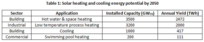
Solar thermal technologies have the potential to
meet a significant portion of global demand for both heating and
cooling. The International Energy Agency’s (IEA) technology
roadmap for solar heating and cooling, published in 2012, outlines
their vision of solar thermal technologies being used to produce
5000TWh of energy annually by 2050, accounting for more than 16% of
energy used for low temperature heating and nearly 17% of energy used
for cooling (see Table 1). The utilisation of solar thermal
technologies on this scale would avoid 800Mt of carbon dioxide
emissions per year [1].
As of 2012, the total installed capacity of solar thermal heating in the UK was 510.1MWth. The energy produced by all of these systems was roughly 210GWh per year, just 0.06% of the total household heat demand and 0.3% of hot water demand [2]. This figure can be considerably improved however, as solar thermal has not been deployed in the UK to the same extent as it has been in other European countries with a similar climate. In Germany, for example, the total installed capacity is roughly 11.8GWhth; this corresponds to an installed capacity of 139.9kWth per 1,000 inhabitants compared with 7.9kWth per 1,000 inhabitants in the UK [3].
92% of the energy provided by solar thermal systems is used to heat domestic hot water. The IEA has identified this application as the most important in which solar thermal systems can be deployed. Indeed, the Energy Savings Trust found in 2011 that a properly installed and operated solar thermal system can meet 60% of domestic hot water demand. Given that the total hot water demand in the UK is roughly 80TWh per year, a reduction of 60% would go a long way to helping us meet our carbon reduction targets and, as a consequence, do much to alleviate climate change.
With the help of the government’s Renewable Heat Incentive (RHI), there are also potential financial savings for the energy consumer who chooses to install a solar thermal heating system. Without RHI however, solar thermal is an expensive form of energy.
Collector types
Solar thermal heating technologies can be divided into two main types: flat plate collectors (FPC) and evacuated tube collectors (ETC).
Solar thermal heating technologies can be divided into two main types: flat plate collectors (FPC) and evacuated tube collectors (ETC).
 Figure 2: Flat plate collector
Flat plate collectors
Although unglazed flat plate collectors are in use, glazed flat plate collectors are far more common. They consist of a metal absorber plate, usually copper or aluminium, which has a selective coating on it to maximise solar irradiation absorption and minimise re-radiation. A series of copper pipes are bonded to the absorber plate, enabling the heat transfer fluid to pass through and carry the produced heat to where it is needed. The plate and bonded pipes are housed within a well insulated metal enclosure, which minimises convective heat losses through the back and sides of the collector, and covered with a transparent sheet of glass, which helps to minimise convective heat losses through the front of the collector while allowing a large portion of the incoming solar radiation to reach the absorber plate. In good quality products, transmission efficiencies are usually 90%, absorption efficiencies 95%, emissions 5% and thermal efficiencies around 78% [4].
Although unglazed flat plate collectors are in use, glazed flat plate collectors are far more common. They consist of a metal absorber plate, usually copper or aluminium, which has a selective coating on it to maximise solar irradiation absorption and minimise re-radiation. A series of copper pipes are bonded to the absorber plate, enabling the heat transfer fluid to pass through and carry the produced heat to where it is needed. The plate and bonded pipes are housed within a well insulated metal enclosure, which minimises convective heat losses through the back and sides of the collector, and covered with a transparent sheet of glass, which helps to minimise convective heat losses through the front of the collector while allowing a large portion of the incoming solar radiation to reach the absorber plate. In good quality products, transmission efficiencies are usually 90%, absorption efficiencies 95%, emissions 5% and thermal efficiencies around 78% [4].
 Figure 3: Evacuated tube collector
Evacuated tube collectors
Evacuated tube collectors are usually made of the same materials as flat plate collectors, but their construction is entirely different. Each evacuated tube usually consists of a copper pipe which is bonded to an absorber fin housed with in a glass tube. The absorber fin and the copper pipe perform the same functions as they do in flat plate collectors, absorbing incoming radiation and passing the produced heat to a transfer fluid which carries it to where it is needed. The glass tube is used to preserve a vacuum in which the heat pipe and absorber fin is housed. As a result, evacuated tube collectors have greater thermal efficiency than flat plate collectors due to the reduced convective heat losses. Transmission efficiencies, absorption efficiencies and emissions are usually about the same as for flat plate collectors, but thermal efficiencies are usually higher at around 83% [4].
Evacuated tube collectors are usually made of the same materials as flat plate collectors, but their construction is entirely different. Each evacuated tube usually consists of a copper pipe which is bonded to an absorber fin housed with in a glass tube. The absorber fin and the copper pipe perform the same functions as they do in flat plate collectors, absorbing incoming radiation and passing the produced heat to a transfer fluid which carries it to where it is needed. The glass tube is used to preserve a vacuum in which the heat pipe and absorber fin is housed. As a result, evacuated tube collectors have greater thermal efficiency than flat plate collectors due to the reduced convective heat losses. Transmission efficiencies, absorption efficiencies and emissions are usually about the same as for flat plate collectors, but thermal efficiencies are usually higher at around 83% [4].
Flat plate collectors are the less expensive option of the two, but they are suitable for most climates. They are particularly well suited to climates in which the collector heat transfer fluid temperature is likely to be between 10°C and 50°C above the ambient air temperature. On the other hand, evacuated tube collectors are the better option for climates in which the heat transfer fluid temperature is likely to be more than 50°C above ambient. They are also better suited than flat plate collectors to low irradiation conditions. This makes them well suited to colder climates [4].
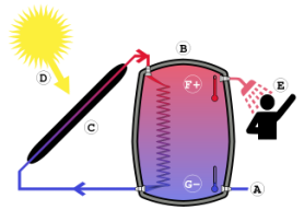 Figure 4: Solar thermal system by Inkwibbna/wikimedia commons, made available under license CC BY-SA 4.0
System configuration
Although the construction of each collector type is entirely different, they both exploit the same fundamental laws of thermodynamics. Radiation from the sun is received on the collector where is its effect is to increase the temperature of the absorber plate (D & C in Figure 4). A heat transfer fluid, usually a water glycol mix, passes through tubes in contact with the absorber plate, absorbing its heat and carrying it to a water storage tank within the dwelling. The heat is transferred to the water storage tank by a heat exchanger which usually occupies the bottom portion of the water tank (unlike Figure 4). Having the heat exchanger in the botom portion ensures that the temperature gradient between the heat exchanger and the stored water is as high as possible, as the water in the lowest part of the tank will be the coolest due to the buoyancy of the hot water causing it to rise to top (F & G in Figure 4). As hot water is drawn off from the top of the tank, cool water enters from the bottom (A & E in Figure 4).
Most solar thermal collectors are unable to meet all of the hot water demand all year round. For this reason, the system will usually have an additional heat input. Whatever the source of the additional heat, it is important for the performance of the solar collector that it enters the tank from the top, as this will ensure that the hot water it provides does not come into contact with the collector heat exchanger - the hotter the water close to the collector heat exchanger, the lower the system's efficiency.
Although indirect systems, in which the heat transfer fluid does not mix with the used hot water (Figure 4) are the most common type of system, direct systems are also in use. These types of systems are only suitable for climates in which there is no risk of the heat transfer fluid freezing throughout the year, however. If there is a risk of the heat transfer fluid freezing due to low ambient temperatures, the heat transfer fluid must contain glycol. This, of course, means that it must be contained within a closed loop, separate from the used water. This is the reason for the popularity of indirect systems.
Most solar thermal systems are pumped systems, meaning that the heat transfer fluid is circulated by a mechanical pump. By contrast, passive systems (sometimes called thermosiphons) do not require any energy input to circulate the heat transfer fluid, instead relying on difference in temperature, and consequently buoyancy, between the heat transfer fluid at the collector outlet and the heat transfer fluid at the collector inlet to power the circulation. Pumped systems are more popular because they offer some level of control, whereas passive systems do not [4].
 Figure 5: UK global horizontal irradiation
Energy availability
The amount of solar heating that will be available depends mostly on how close to the equator you live. Although all regions in the UK are suitable for solar thermal systems, the average annual solar irradiation varies from about 1200kWh/sq m on the south coast to 900kWh/sq m at the north of Scotland. Added to this the difference in ambient temperatures of both regions, which has a significant impact on heat losses. The performance of a solar thermal system could therefore vary greatly depending on where it is installed. Systems installed in the southern part of Europe will understandably be exposed to much higher levels of solar irradiation and temperatures and will therefore typically perform better.
To correct for the distance north of the equator, solar collectors are normally inclined from the horizontal to maximise the amount radiation they are exposed to throughout the year. In the UK the optimum angle of inclination is between 30 and 40 degrees for a south facing panel. This has the effect of reducing the amount of radiation that the panel is exposed to during the summer months but increasing the amount it is exposed to during the winter months. The result is better year round performance [4].
why integrate biomass and solar thermal?
In theory, biomass and solar thermal are two complementary technologies.
In winter biomass boilers may operate at an optimal efficiency rating over a sustained period of time to meet a fairly consistent demand for space heating, with intermittent solar thermal contributions supplementing when available to reduce biomass dependency (with equivalent carbon emission reductions and financial savings). However, biomass boilers are not well suited for summer operation due to their poor turn-down ratio i.e. they are sized to satisfy peak winter loads and cannot satisfy typically low summer heating loads at optimal operating efficiency. Fortunately, a correctly sized solar thermal system in integration should be sufficient to satisfy most if not all of the summer hot water demand, where in typical northern hemisphere climates the demand for space heating will be low or most likely non-existent. Integrating biomass boiler systems with solar thermal paneling therefore provides the opportunity to size the biomass optimally for winter without consideration to any potential summer oversizing.
In winter biomass boilers may operate at an optimal efficiency rating over a sustained period of time to meet a fairly consistent demand for space heating, with intermittent solar thermal contributions supplementing when available to reduce biomass dependency (with equivalent carbon emission reductions and financial savings). However, biomass boilers are not well suited for summer operation due to their poor turn-down ratio i.e. they are sized to satisfy peak winter loads and cannot satisfy typically low summer heating loads at optimal operating efficiency. Fortunately, a correctly sized solar thermal system in integration should be sufficient to satisfy most if not all of the summer hot water demand, where in typical northern hemisphere climates the demand for space heating will be low or most likely non-existent. Integrating biomass boiler systems with solar thermal paneling therefore provides the opportunity to size the biomass optimally for winter without consideration to any potential summer oversizing.
references
[1] International Energy Agency, “Technology Roadmap: Solar Heating and Cooling,” International Energy Agency, Paris, 2012. [Online]. Available: http://www.iea-shc.org/data/sites/1/publications/Solar-Heat-Worldwide-2014.pdf
[2] Department of Energy & Climate Change, “The Future of Heating: A strategic framework for low carbon heat in the UK,” March 2012. [Online]. Available: https://www.gov.uk/government/uploads/system/uploads/attachment_data/file/48574/4805-future-heating-strategic-framework.pdf. [Accessed April 2015].
[3] F. Mauthner and W. Wiess, “Solar Heat Worldwide,” June 2014. [Online]. Available: www.iea-shc.org/data/sites/1/publications/Solar-Heat-Worldwide-2014.pdf
[4] Building & Engineering Services Association, “Solar Thermal,” Building & Engineering Services Association, [Online]. Available: www.b-es.org/sustainability/sustainable-technology-briefing-sheets/solar-thermal-guidance/