Hybrid Energy Systems in Future Low Carbon Buildings
 
Scope  
Background  
Micro wind  
Heat pumps  
Heat recovery  
Solar thermal panels  
Pv  
Bipvt  
Chp  
EarthToAir heat exchange  
Passive design  
Thermal storage  
Design concept  
Hybrid concept  
Methodology  
Modelling tools  
Case study results  
Environmental impact  


Earth to air heat exchange through buried pipes

Earth to air heat exchange

Earth tubes are low technology, sustainable passive cooling-heating systems utilized mostly to preheat a dwelling's air intake. Air is either cooled or heated by circulating underground in horizontally buried pipes at a specified depth.

Specifically air is sucked by means of a fan or a passive system providing adequate pressure difference from the ambient which enters the building through the buried pipes. Due to ground properties the air temperature at the pipe outlet maintains moderate values all around the year. Temperature fluctuates with a time lag (from some days to a couple of months) mainly relative to the depth considered. Temperature values remain usually in the comfort level range (15-27 °C).

This technology is not recommended for cooling of hot humid climates due to moisture reaching dewpoint and often remaining in the tubes. However there are southern European coastal regions as in Greece where the climate remains hot and dry. In such locations these systems could have impressive results.

The material of a pipe can be anything from thin wall 'sewer' plastic, metal or concrete. However concrete should better be avoided in order not to be dependent on carbon filtration UV sterilization for the musty air coming out of concrete earth tubes.

The effectiveness of a buried pipe system is mainly related to the following parameters:

  • Ground temp. at depth of the installed exchanger
  • Thermal diffusivity of soil
  • Pipe length, width
  • Inlet air temp.
  • Thermal conductivity of pipes
  • Air velocity
Our model

In the model we have developed, we have considered an open loop earth to air heat exchanger including a 60 m low conductivity pipe of 0.10m diameter, 3m underground at a moderate air velocity of 11m/s provided by a fan (300W power consumption) for a grass soil (ESP-r summary and full report).

Ground temperatures

The ground temperature was approximated to be 15-17 degrees (yearly variation) based on parameters mentioned above (Mihalakakou 1994) and the fact that local maximum temperatures in Palermo don't exceed 30°C so often. Usually those varied between 23-30°C for a summer period (ESPr Palermo data file) significantly lower than 23-38C in Mihalakakou's report. Furthermore these values were compared to Jacovide's article used also by the Hellenic national observatory. In this case a grass surface's mean and summer value at 2 m depth for Greece's higher temperatures were 18.5C and 23.5C respectively.The ground's temperature monthly values are illustrated below in °C :

JAN FEB MAR APR MAY JUNE JULY AUG SEPT OCT NOV DEC
14.5 14.0 14.5 15.0 15.5 16.0 16.5 17.0 16.5 16.0 15.5 15.0


Air flow calculations

In order to calculate the mass flow rate of the model's pipes we have used the equation:


Air flow rate
Air flow rate
leading to the air flow rate being:


The power value used in the above equation is the max power required instantaneously by the two zones in the period assessed as noticed in ESP-r cooling results.
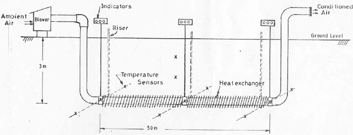
As the flow rate is v=0.087m3/s and the cross section area is equal to 0.0078m2 the required velocity of the air through the pipes is 11m/s.

For the estimation of the convection coefficient we have used the following equation:

Nu

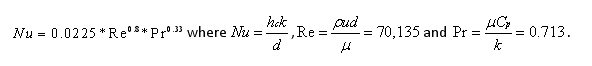
From the above the convection coefficient is: hc=39.76W/m2K.

The sizing of our system and optimum values regarding air flow rate and velocity where influenced by similar cases in literature relating to climatic conditions and system magnitude, power consumption and thermal load output.
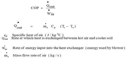
Thermal COP values

Coefficient of performance is a measure of heat exchanger efficiency. It is defined as (ASHRAE 1985). COP values mentioned bellow regard the energy output to input ratio. Input values are the energy consumed by the blower (300W) and output energy is the cooling or heating thermal energy introduced in a building.

COP


Ventilation

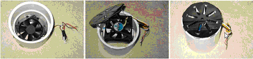
 ◊ Mechanical

Ventilation can be managed through a terminus box ('plenum') and be fan powered or individually fan assisted by installing a 10 cm axial fan in the end of each tube in case of more tubes than one. At day time ventilation could be powered by a PV system located upon the roof.


In our case we have considered a similar system with prof Sharan's report (5) utilising a 400W rated ventilator. Actual energy consumption for a mass flow of approximately 0.1 m3/s and an air velocity of 11 m/s would add up to rouhly 300Wh per hour.

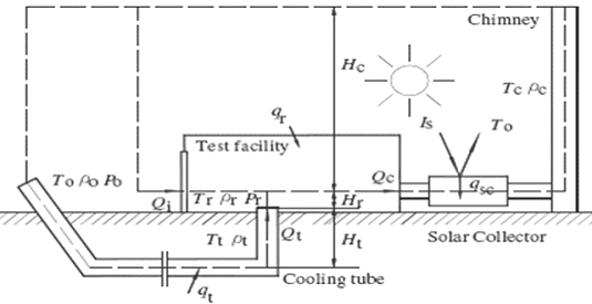
 ◊ Passive ventilation

Passive ventilation through the combination of a solar chimney and solar panels is an alternative to a fan.

A solar chimney could be connected to solar panels (heating air) on ground level increasing air temperature inside the base of the chimney. This would lead to air mass expanding and creating a draft through the chimney due to pressure difference.

Negative pressure would be created and if well sealed the pressure difference would result in passive ventilation due to air pulled through the buried pipe at an adequate flow rate.

Low infiltration from walls and openings has been considered as well as friction reducing the flow rates and has been deducted from the chimney flow rate in order to estimate that of the buried pipe.

Passive ventilation

Link to our model

Our ESP-r earth to air heat exchange model (located in Palermo) had similar specifications and climatic conditions with the report of the University of Nebraska (7). Specifically similar values where considered concerning pipe air flow, ground temperatures-depth, local climatic conditions, leading to a natural air flow of 0.13 m3/s (afternoon hours) in the solar chimney. This was 0.043m3/s more than the requirement (0.087 m3/s) of our model.

Concerning the summer period, deducting a minimum flow of 0.012 m3/s (infiltration rate of the dwelling structure) from the chimney's flow could replace an energy equivalent (due to the fan's reduced operation) of:
3(months)*10 (daylight hours)*0.3 (kW power) = 276kWh.

Unfortunately, the 20m2 solar collector area reported in literature (7) in combination with certainties regarding necessary pressure differences, complexities due to friction in the buried pipes and the fact that this system was only functional for daylight hours discouraged further evaluation of this scenario.


Conclusions

The efficiency values we were expecting for Southern Europe were compared to Baxter's facility at Knoxville, Tennessee (USA) which was consisted of a similar sized pipe, climatic conditions and site latitude. Specifically the mean hourly values for the entire period of test ranged from COP= 1.4 to 2.69. During these periods basic soil temperature varied from 14.8°C to 18.2°C.

Using the above COP equation and considering our flow rate, an average pipe outlet temp of 19°C and an average inlet in summer of 25°C the estimated COP value is roughly 2.1.

ESP-r results agree for the 10:00-19:00 hour (COP=2) decreasing to a value of 1.6 when operating all day, as during the night temperature differences decrease considerably.


References:

1. Earthtubes (earthtubing) non-electric heating, passive geothermal low-tech solar heating & solar cooling systems for sustainable architecture
2. Santamouris M., Mihalakaha G. Balaras C.A. Argirioua Asimakopoulos D. and Vallinaras M. (1995). Use of Buried pipes for energy conservation in cooling of agricultural greenhouse. Solar Energy. Vol. 35 PP 111-124
3. C.P. Jacovides, G. Mihalakakou, M/ Santamouris, J.O. Lewis: On the ground temperature profiles for passive cooling applications in buildings. Solar energy journal Vol.57, No 3.
4. Baxter, D.O. (1992) Energy exchange and related temperature of an earth-tube heat exchanger in heating mode. Trans ASAE, 35 (1) : 275 - 285.
5. Performance of Single Pass earth-Tube Heat Exchanger: An Experimental Study, Prof Girja Sharan
6. ASHRAE (1985). Handbook of application. Atlanta Ga. American Society of Heating Refrigerating and Air Conditioning engineers Inc.
7. Performance of single pass earth-tube heat exchanger: an experimental study