Renewable Energy resources
Renewable Energy Technologies allow the production and distribution of different energy forms such as electrical and heat from renewable sources. The most popular renewable sources include, but are not limited to; solar, hydro, geothermal and wind with the latter being very popular in the UK, and especially Scotland. For the scope of this project, energy generated from wind will be given a higher importance as discussed in the Short Term Operating Reserve and the Future Electricity Prices section, in addition to Findhorn generation. Figure 1 shows a set of wind turbines from Findhorn.

Figure 1. Wind Turbines from Findhorn. (C) Joe Schnaier
electrolyser
An electrolyser is a system of components which is used to perform electrolysis. Electrolysis is a process where different chemical compounds are split using an electrical current. In the example of water electrolysis, an electric current separates a water molecule into hydrogen and oxygen. Table 1 summarises the different categories of electrolysis cells, which are characterised per the electrolyte utilised for ion transport.
Table 1. Electrolysis Cell Types Source: [2]
Table 1. Electrolysis Cell Types Source: [2]
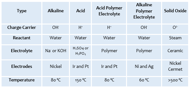
Table 1. Electrolysis Cell Types [2]
For large-scale industry, an Alkaline Electrolysis - APEEC (Figure 2) is more commonly used, mainly due to the cheap materials and high durability resulting from the use of high corrosion resistance stainless steel materials and robust cell separators. One drawback of such a system lies in the fact that the hydrogen is produced at a low pressure, thus arising the requirement of a compressor.
An Acid Polymer Electrolysis – PEMEC (Figure 2) is the latest technology. PEMEC have several advantages over APEEC, one of which being the higher energy efficiency. A Higher hydrogen production can result from using such system. PEMEC however come at a higher capital cost as a consequence of using valve metals in the cells, costly materials as catalyst, and a high cost polymer electrolyte. [2]
An Acid Polymer Electrolysis – PEMEC (Figure 2) is the latest technology. PEMEC have several advantages over APEEC, one of which being the higher energy efficiency. A Higher hydrogen production can result from using such system. PEMEC however come at a higher capital cost as a consequence of using valve metals in the cells, costly materials as catalyst, and a high cost polymer electrolyte. [2]

Figure 2. Schematic Diagram of APEEC and PEMEC [2]
Hydrogen compressor
Compression is an essential part in hydrogen delivery through the pipelines. This process is carried out with the use of a hydrogen compressor, which increases the pressure of the hydrogen to an adequate value for transmission and storage. Figure 3 shows a typical Hydrogen Compressor with a range of prices between £40,000 and £200,000. Apart from having a high capital cost, such systems require large amount of energy for operation, and also require high maintenance costs.
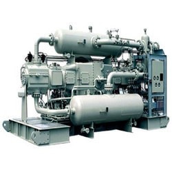
Figure 3 Hydrogen Compressor. Source [3]
The typical Hydrogen Compressors are either Piston (or Reciprocating) or Rotary Compressors. Table 2 summarises the characteristics of each. [3] [4]
Table 2. Compressor type Source: [3]
Table 2. Compressor type Source: [3]
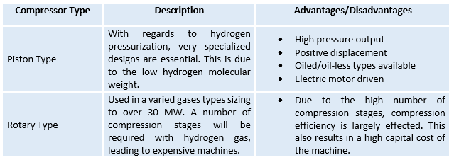
Table 2. Compressor Type Comparison [3]
hydrogen storage tanks
Hydrogen has a high volumetric energy density when compared to gravitational potential energy, thus large amounts of energy can be stored. When compared to liquid hydrocarbon, hydrogen also has a larger amount of chemical energy per unit mass, this being 142 MJ/kg as opposed to 47 MJ/kg.
Hydrogen can be either stored in a liquid or gaseous state. Hydrogen will be pressurised following the compressor in order to occupy a smaller space. Figure 3 shows a typical large scale hydrogen storage tank. [5]
Hydrogen can be either stored in a liquid or gaseous state. Hydrogen will be pressurised following the compressor in order to occupy a smaller space. Figure 3 shows a typical large scale hydrogen storage tank. [5]
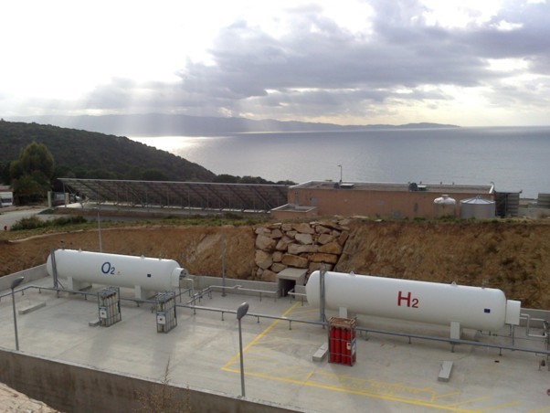
Figure 3. Hydrogen Storage Tank Source: [8]
fuel cell
A fuel cell is similar to a battery, both having an electrolyte, negative and positive electrodes as shown graphically in Figure 4. Differing itself from a battery however, a fuel cell requires a constant supply of fuel and oxidant. The electrodes within a fuel cell do not undergo any chemical reaction but rather an electrochemical one which occurs at the surface of the catalyst and the interface between the electrolyte and the membrane. [6], [7]

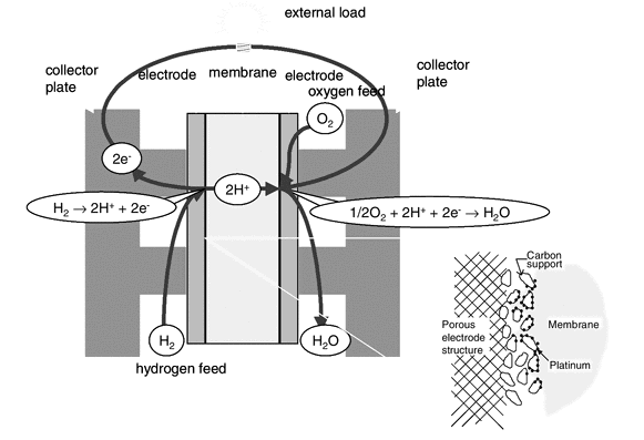
Figure 4 Basic Principle of a Fuel Cell
[1] https://energy.gov/eere/wind/animation-how-wind-turbine-works
[2] P. T. M. &. J. Garche, Electrochemical Energy Storage for Renewable Sources and Grid Balancing, Waltham, MA: Elsevier B.V, 2015.
[3] R. B. Gupta, Hydrogen Fuel: Production, Transport, and Storage, Boca Raton: Taylor & Francis Group, 2009.
[4] Directory, Business, Air Equipments, and Hydrogen Compressor. "Hydrogen Compressor - Suppliers, Manufacturers & Traders In India". Dir.indiamart.com. N.p., 2017. Web. 29 Mar. 2017. [Online]
[5] D. P. Broom, Hydrogen Storage Materials: The Characterisation of Their Storage Properties, London: Springer-Verlag, 2011.
[6] N. Sammes, Fuel Cell Technology, New York: Springer, 2010.
[7] F. Barbir, PEM Fuel Cells, California: Elsevier, 2013.
[8] http://c1cleantechnicacom-wpengine.netdna-ssl.com/files/2013/12/Myrte-2.jpg. [Online].