-
The demand for electricity varies hourly, daily and seasonally. In traditional power systems, the generation can be adapted to these variations thanks to a mix of energy sources: nuclear and coal are used for the base load and gas turbines or pumped hydro, which are systems that can respond fast, are used to meet the fluctuations in demand.
If it is wished to integrate renewable sources to a network, in order to be able to decrease its dependency to the grid, there will be issues regarding intermittency of renewable generation. Actually, these kinds of supply have times at which they are abundant but those times will not necessarily coincide with the consumer demand. In order to cope with this problem, the surplus of electricity from renewable supply can be stored and used afterward, when there is a demand with no generation available. Electrical Energy Storage (EES) will therefore increase the use of on-site renewable generation. However these systems are not perfect and there will be some losses of energy.
In the context of Eco-communities, it can be seen that they are showing the will to be more sustainable. It was seen that they often put a lot of different renewable supply in order to meet their demand and decrease their dependency to the grid. Even if the grid can be seen as a very efficient system to balance supply and demand, there are 2 main issues that pushed eco-villages to decrease their dependency to the network:
- Ecological philosophy: The electricity from the grid is not necessarily clean and is widely dependant on fossils fuels and/or nuclear supplies.
Electricity storage in an Eco-village would help increase the use of its own generation which the sources are known
and approved by the community.
- Economic matters: In the example of Findhorn, the surplus from renewable is sold at a much lower price than the charge paid when electricity is imported.
For the above reasons, it was decided to inquire about a suitable and feasible electrical storage system for Findhorn community.
It was decided that just one technology will be investigated, in order to narrow down the subject and have time to produce some results. The first step was then to evaluate what technology would be interesting to study. The chosen system was then more deeply investigate and some solutions were proposed.
-
Description of technologies
When starting the project, it was evaluated that Electrical Energy Storage (EES) was an interesting topic to integrate and could have benefit to the community. However there was no particular type of technology specified.
First, it has to be understood that there are 2 main functions that EESs can achieve, and for each of it , different technology are used. There are the systems that can store large power in small quantity. Those are used for emergency power, when the main power source fails for example (Uninterruptible power supply, UPS), or for providing power quality. The second kind of EESs can store smaller power in larger quantity and are used for energy management. The figure below illustrates which technologies are more suitable or each of these functions.
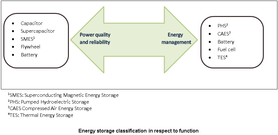 Source: (Haisheng Chen, 2009)
In the case of Findhorn, it was easily seen that the technologies wished to be used were the one concerning the energy management of electrical systems. Moreover it was known that the size of the EES should corresponds to small to medium scale therefore Pumped Hydroelectric Storage and Thermal Energy Storage, that are mostly used for large scale, were not investigated. In the following part, electrical batteries, flow batteries, hydrogen fuel cell and compressed air energy storage will be briefly described and the main advantages and drawbacks of each of these technologies will be presented.
Electrical Batteries
Batteries are the oldest form of storing electricity and therefore the best known and mature. There are a wild range of different batteries using different chemical reactions but in this review, just the general characteristics will be exposed.
Batteries can transform chemical energy into electrical energy, and vice versa, using electrochemical reactions (H. Ibrahim, 2008). They are composed of one or more electrochemical cells. Each of these cells consist of a positive electrode (Anode) and a negative electrode (Cathode) separated by an electrolyte which is able to conduct ions between the two electrodes (R.M. Dell, 2001).
Batteries can respond quickly to load changes and provide system stability, while having low standby losses and high energy efficiency (60-95%). However, they have a high maintenance costs, a short cycle life, a limited discharge capacity and some type of batteries need thermal regulation (Haisheng Chen, 2009). Besides, they should be regards concerning the recycling as they usually use toxic materials (DTI, 2004).
Redox flow Batteries
As for batteries, there are different kinds of flow batteries. However, only the general characteristics of this type of storage system will be presented here.
A flow battery is based on the combination of 2 half simultaneously separate electrochemical reaction. The difference with normal battery is that the energy is stored in the electrolyte solution made from electro active species that have to be pumped into the power cell to convert chemical energy into electricity (V. Amstutz, 2012) . Hence, this system comprises 2 tanks storing the solutions, 2 pumps and a power cell.
This system provides large range of power/energy ratios, with long lifetime, along with the advantages stated before for the classical batteries. However it has a complex architecture with risks of leak in the electrolyte and can have high maintenance cost (CEA, 2012) .
Hydrogen Fuel Cell Storage
The hydrogen is produced from an electrolyse. To charge the system the electricity is coupled with water to produce hydrogen and oxygen. The hydrogen is then stored and used when needed by passing it, with oxygen (air), through a fuel cell to create electricity and water. A basic hydrogen storage system is composed of an electrolyser unit, a hydrogen storage tank and a ydrogne energy conversion system, commonly a fuel cell.
These systems have a lot of advantages including a high energy density, an ability to be implemented over a large range of scales and opportunities for CHP (Haisheng Chen, 2009). However they are a new technology that are costly, with still a fairly poor efficiency.
Compressed Air Energy Storage (CAES)
In CAES, electricity is used to run a compressor and compressed air that is then stored and expand in a turbine to produce electricity when needed.
This simple system has just recently been adapted for small to medium scale. It can store the energy for a very long period of time, and can provide high power and capacity. However it efficiency it still quite low and method for better management of heat transfer should be integrated.
Selection of a technology
The table below summarize the main aspect of the different technologies investigated:
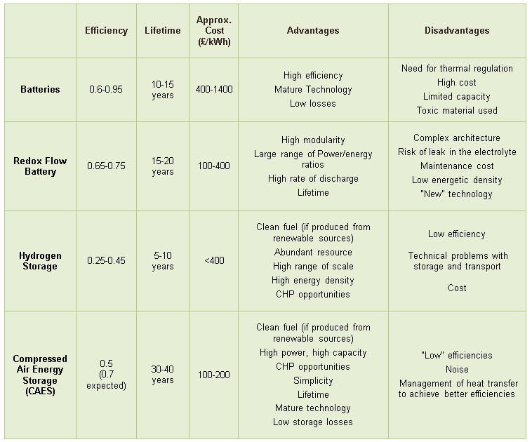 Source: (CEA,2012)(Haisheng Chen, 2009)
Regarding the choice of the technology that could be used, Findhorn community was keen to see the performances of flow batteries because it looked like a promising technology and that governments and organisations are putting money to experiment it. In Scotland, the Isle of Gigha is already undertaken a project to install a flow battery, financed by the UK government (£3.6 millions) (Journal, 2013). This example has been looked at, because the size of Gigha corresponds to the size of the community with a similar amount of wind generation. It has been seen that they will used a 1.26 MWh Vanadium Redox flow battery. However the main drawback was that this system was that it would use 75,000 litres of sulphuric acid mixed with vanadium pentoxide (DOE, 2012) and we thought that that might be a problem for an Eco-community. Other choices were then looked at.
From the above table, it can be seen that CAES seems to be very cost-effective and to have a lot of advantages. It looks like one of the more attractive option. Moreover, there are a lot of expectations regarding the future of this technology and the adaptation of this mature technology in a new fashion could lead to high efficiencies with a relatively low cost (especially compared with the price of batteries). A lot of recent papers were found and it was seen, in this first review of storage technologies, that almost no drawbacks were suggested. It was thought that an analysis of CAES could be interesting to have a better understanding of this this system and see how it could be proposed and implemented for Findhorn community.
References
CEA. (2012) "Le stockage stationnaire de l'énergie". Commissariat à l’énergie atomique et aux énergies alternatives
DOE. (2012) "Gigha Wind Farm Battery Project". Retrieved from DOE Global Energy Storage Database: http://www.energystorageexchange.org/projects/774
DTI. (2004) "Review of Electrical Energy StorageTechnologies and Systems and of their Potential for the UK". Crown State.
H. Ibrahim, A. I. (2008) "Energy storage systems—Characteristics and comparisons". Renewable and Sustainable Energy Reviews, 1221–1250.
Haisheng Chen, T. N. (2009) "Progress in electrical energy storage system: A critical review". Progress in Natural Science, 291-312.
Journal, E. S. (2013) "REDT provides windy Scottish island with flow battery storage system". Retrieved from Energy Storage Journal: http://energystoragejournal.com/redt-provides-windy-scottish-island-with-flow-battery-storage-system/
R.M. Dell, D. R. (2001) "Understanding Batteries". The Royal Society of Chemistry.
V. Amstutz, K. T. (2012). Les batteries redox pour le stockage d’énergie. electrosuisse.
-
Large scale plants
Nowadays, there are only 2 existing CAES plants in the world: one in Huntorf in Germany and another in McIntosh in USA. Those 2 plants use off-peak electricity generation to compress air. This later is then stored into underground salt caverns. During peak power it is injected in a combustion chamber to heat it up (with natural gas, generally) and then expands into a turbine to provide electricity. The operation of these systems is illustrated below:
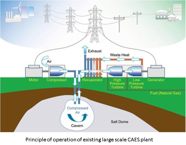 ©Copyright: INTECH
Huntorf is the first commercial CAES plant. It is operational since 1978 and has a rated power of 321 MW which can be provide for 2h. The compressed air is stored in 310,000m3, 600m depth salt caverns (DOE, 2012).The 2nd commercial CAES plant, McIntosh, is in operation since 1991.It can provide 110MW for 26 hours. (DOE, McIntosh CAES Plant, 2012)
The difference between those 2 plants is that McIntosh integrates a waste recovery system that allow pre-heating of the air before the combustion chamber, hence less gas is necessary to heat the compressed air up.
The efficiency of these conventional CAES plant is low and usually do not exceed 40%, essentially because they have to use an external fuel to heat the compressed air before the expansion. New generation of CAES plant are being investigated in order to increase the efficiency. For example, in Germany the project ADELE is investigating adiabatic compression. This is based on the fact the air is heated during the compression. ADELE project is trying to store this heat with advanced Thermal Storage Energy (TES) systems so that this heat can be re-injected in the expansion stage and the use of external fuel avoided (RWE, 2010). The efficiency of this king of technology is expected to reach 70% and therefore looks like a very promising method for energy storage.
Adaptation in a small scale
The adaptation of CAES in a small scale is very recent and the first prototypes are just appearing.
In large scale CAES it was seen that the air is stored in large underground caverns. That makes the system dependant on geological aspects and cannot be placed everywhere. The idea to adapt this technology to small scale is to be able to store the air in man-made vessels that make it a more adaptable solution, especially for distributed network (Younmin Kim, 2008), i.e. communities in this project.
Moreover to adapt the system to small scale, there is a need to work with high pressures, which results in unsteady state process, where the pressure ratios are changing. As compressors and turbines are working under determined conditions, these variations can reduced the overall efficiency of the system (Kim, 2012).Solutions have been proposed to provide constant-pressure air storage but this method will not be analysed in this project.
For the management of heat transfer in the small scale system, isothermal CAES, that can minimize the compression work while maximizing the expansion work, are under research. Some companies, like SustainX's have recently produced some prototype that used hydraulic pumps and motors.(Young-Min Kim, 2012)
Such a system can be seen below:
 © Copyright: http://dailyfusion.net
References
DOE. Kraftwerk Huntorf(2012) "Retrieved from Doe Global Energy Storage Database". http://www.energystorageexchange.org/projects/1245
DOE. McIntosh CAES Plant (2012) "Retrieved from DOE Global Energy Storage Database". http://www.energystorageexchange.org/projects/136
Kim, Y. M. (2012) "Novel concepts of compressed air energy storage and thermo-electric energy storage". ÉCOLE POLYTECHNIQUE FÉDÉRALE DE LAUSANNE.
RWE. (2010) "ADELE – ADIABATIC COMPRESSED-AIR ENERGY STORAGE FOR ELECTRICITY SUPPLY". Retrieved from RWE Corporate website: http://www.rwe.com/web/cms/mediablob/en/399030/data/0/2/ADELE-Adiabatic-Compressed-Air-Energy-Storage-for-electricity-supply.pdf
Young-Min Kim, J.-H. L.-J. (2012) "Potential and Evolution of Compressed Air Energy Storage: Energy and Energy Analysis". Entropy, 1501-1521.
Younmin Kim, D. F. (2008) "Energy and Energy Analysis of a Micro Compressed Air Energy Storage and Air Cycle Heating and Cooling System". International Refrigeration and Air Conditioning Conference (p. 2149). Purdue e-Pubs.
-
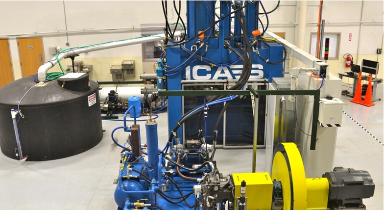
EES software
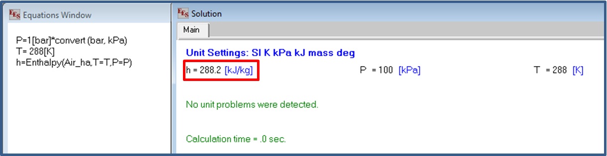
Engineering Equation Solver (EES) is a commercial program which major feature is to provide high accuracy thermodynamic and transport property database for hundreds of substances. It is used to solve non-linear simultaneous equation. The user can input equations with references to a property of a special substance, as it can be seen below in a simple example, where the enthalpy of the air at 1 bar and 288K (15 oC) has to be found:
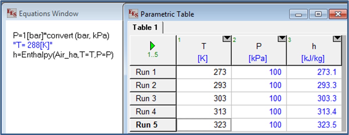
The software contains parametric tables that allow comparison between some variables. A given parameter can be isolated in the equation window and its value can be modified in the parametric table. From the above simple equation, we can then see what happen to the enthalpy if the temperature is changed for example:
Understanding of CAES with EES software
Gas cycle thermodynamics analysis
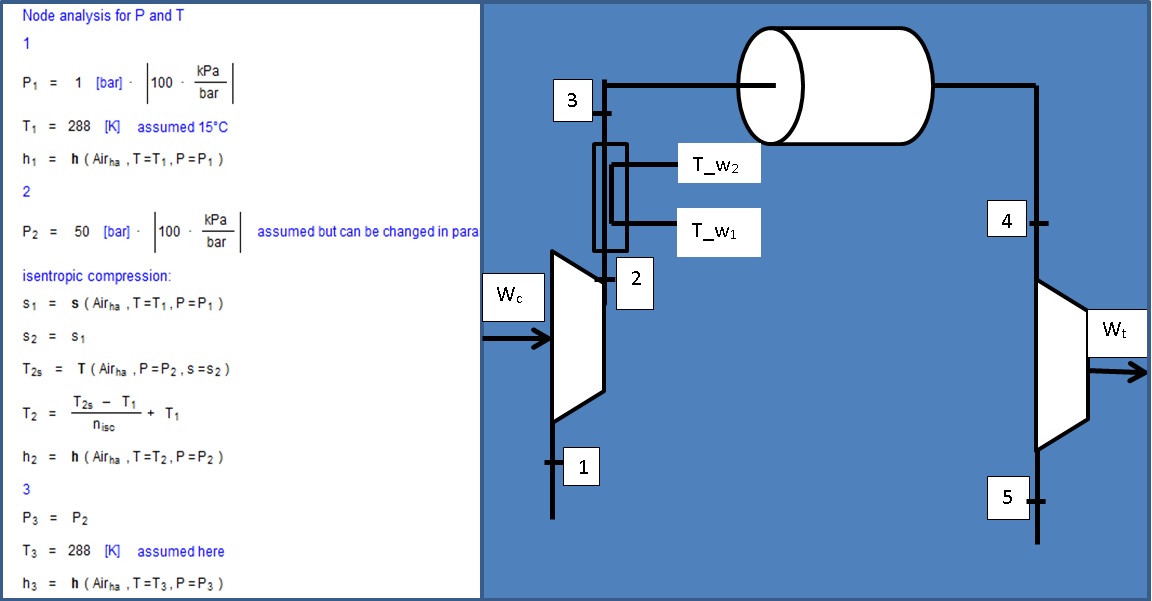
In order to understand CAES, a simple gas cycle analysis was modelled in EES. An overview of this version can be seen below and the model can be found here: Simple model (can only be open if EES is installed on the computer)
Few assumptions were made in order to simplify the system:
- The isentropic efficiencies for compression and expansion are 0.8.
- The temperature of the air entering the system is 15 oC. This is also taken as the outside temperature.
- The temperature of the air stored is equal to the outside temperature, 15 oC.
- The possible pressure drop inside the storage tank is ignored.
A node analysis will give the temperature T, the pressure P and the specific enthalpy h for each node 1,2,3,4 and 5. Those values are then used to calculate the compression work Wc and the turbine work output Wt, along with the energy required for compression Ec and the energy delivered by the turbine, Et.
The following equations were used:
Wc = mc x (h2 - h3), where mc is the air mass flow entering the compressor in kg/s.
h1 and h2 are the specific enthalpy in node 1 and 2 respectively, in kJ/kg.
Wc is in kW.
Ec = Wc x tc ,where tc is the time of compression in h (the calculation of this time are explain below).
Ec is in kWh.
Wt = mt x (h4 – h3), where mt is the air mass flow entering the turbine in kg/s.
h4 and h3 are the specific enthalpy in node 4 and 5 respectively, in kJ/kg.
Wt is in kW.
Et = Wt x t, where t=12h is the time of expansion(see section below).
Et is in kWh.
Those values allow the calculation of the work ratio Wr and of the thermodynamic efficiency, n. However, to see if the system is feasible, the volume of the storage tank and the time of compression needed to be calculated.
Volume of the storage tank and time of compression calculations
The volume of the storage tank, V, in m3, was calculated assuming that the output work from the turbine Wt was wanted to be maintained for 12h. Hence t= 12h. The storage pressure was taken as the pressure in node 3, P3. The density of the air in the storage tank was found in the property table of EES, considering this pressure and the storage temperature. The volume flow rate in m3/s was then calculated by dividing the mass flow entering the turbine (kg/s) by the density (kg/ m3). Finally multiplying this volume flow rate by the time gives the volume of the air V that need to be stored if the work output from the turbine if wished to be maintained for 12 hours.
The time for compression, Tc, is the time necessary to compress the amount V of air. To find it, the specific volume, in m3/kg, of the air at the exit of the compressor was obtain in the property table. By multiplying it by the mass flow entering the compressor, the volume flow rate at the exit of the compressor was found. The volume of the storage tank divided by this value gives the time of compression.
-
In this part, an initial system was put into the model created. The characteristics entered for the initial system were the following:
- The mass flow entering the turbine mt is 0.1 kg/s.
- The output pressure from compression, P2, is equal to 9 bar.
- The input temperature of the turbine, T4, is assumed to be the outside air temperature, 15 oC.
- The mass flow entering the compressor, mc, is equal to 0.1 kg/s.
With the help of the parametric table, the above characteristics were changed and conclusions about the system behaviour were drawn.
Modification of the mass flow entering the turbine
The mass flow entering the turbine mt was changed from 0.1kg/s to 1 kg/s in a parametric table. The results are shown below:
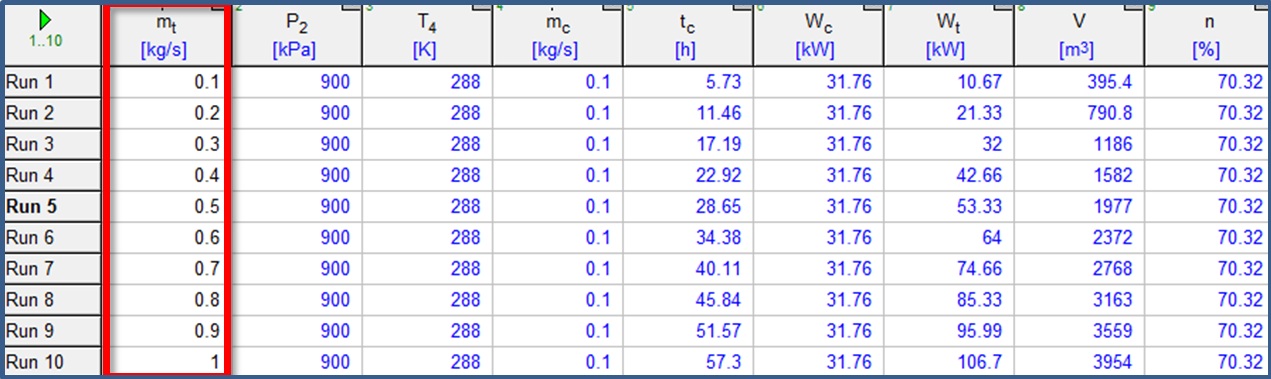
First, it can be seen that a modification of the mass flow leads to variations in the work output Wt , the volume of the storage V and the time of compression tc.
Actually, if mt is increased, Wt rises. As this work output is assumed to be maintained for 12 hours, the capacity of the storage is consequently increased. For mt=0.1 kg/s, the work output is very low but it can reach more than 100kW (which correspond to a capacity of 1200kWh) with a high mass flow. However this increment of mt also make the time of compression to raise a lot along with the volume of the storage tank.
From the table, it can be observed that the efficiency is constant and very high for this system. Though, the volume of the storage tank is so high compared to the available energy from the CAES that this system will not be achievable in practice.
In the further analyses, the mass flow was set to 0.5 kg/s in order to achieve an appropriate capacity for the storage system.
The mass flow entering the turbine can be used to maximise the work output (i.e. the capacity in this model); yet, considerations should be made regarding the volume of the storage tank and the time of compression.
Modification of the output pressure from compression
The output pressure from compression, P2, was changed from 9 bar to 250 bar in a parametric table. The results are shown in the table below:
(The pressure is expressed in kPa in EES, 1 bar = 100kPa)
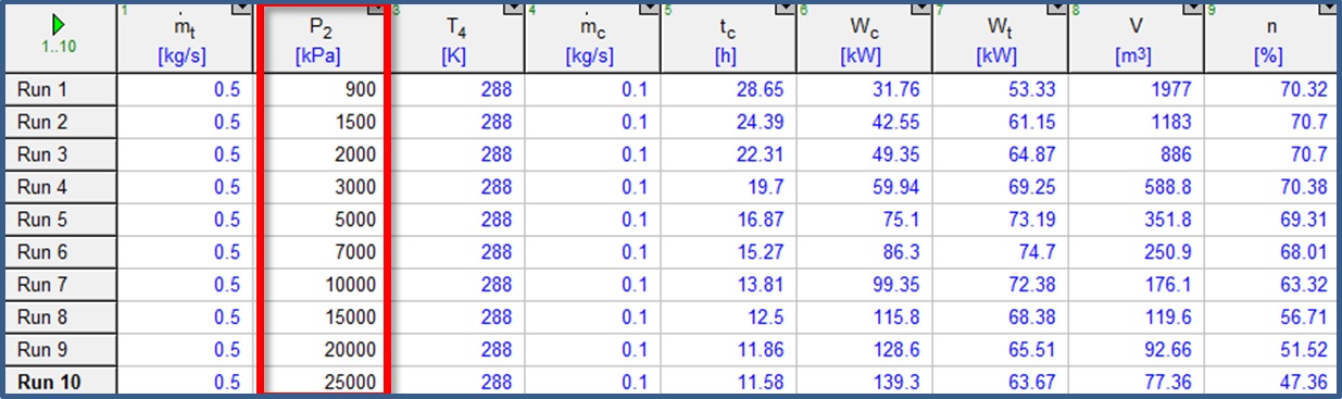
As P2 is getting higher, the work required to compress the air is logically increased by quite a large amount but the time of compression is decreased. At the same time the work output is first augmented with a peak at 70 bar, but then decreased slowly for higher pressure.
One of the main aspect observed in this table is that the volume of the stored air is largely decreased when P2 is high. This can be very useful in our case where the storage of the air has to be done in surface and not in large underground caverns. However it can be seen that this increment of pressure leads to a big decrement of efficiency.
For practical reasons, regarding the volume of the storage tank which needs to be of a reasonable size, the pressure will now be set to 200 bar and it will be seen if the efficiency could be improved.
The output pressure from compression P2 can be used to minimise the volume of the storage tank; yet, considerations should be made regarding the overall efficiency of the system.
Modification of the input temperature of the turbine
The input temperature of the turbine, T4, was changed from 0 oC (272K) to 427 oC (700K) in a parametric table. The results are shown in the table below:
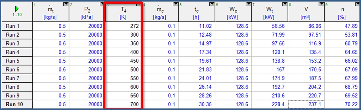
As T4 is getting higher, the time of compression is increased while the work required for compression is remaining constant. The work delivered by the turbine in largely increased and the efficiency can reach more than 70%. The volume of the storage tank is increased but is still remaining between feasible limits.
In the last analysis, this temperature will be reset to 15 oC, keeping in mind that it can have a very good influence in the system.
The input temperature of the turbine, T4 can be used to maximise the work output and the efficiency of the system.
Modification of the mass flow entering the compressor
The mass flow entering the compressor, mc, was changed from 0.1 kg/s to 1 kg/s in a parametric table. The results are shown below:
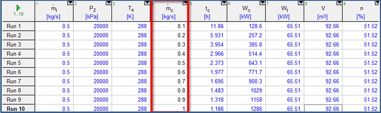
If the mass flow entering the compressor is increased, the only changes occur in the compressions stage: the time of compression is decreased while the work for compression raised dramatically.
The mass flow entering the compressor, mc, has influences on the time of compression and on the work for compression but do not changes any other parameters.
-
Compression side
In the sensitivity analysis, it was seen that one of the major parameter to take into account in the adaptation of CAES for small scale was the pressure at the output of the compressors. Actually, if this pressure is increased the volume of the storage tank is decrease and allows feasible size of tank for small scale. For this reason, it was decided to inquire about compressors that could compress up to 200 bar.
Industrial companies were contacted in order to obtain more data about the real performances of compressors. The first interrogation was to know what kind of power and mass flow capacity was needed for the compression stage. It was seen that, for a fixed power, the higher the power, the higher the mass flow capacity. Moreover it was observed, in the sensitivity analysis, that if the mass flow is high the time of compression is reduced.
As the community has a high amount of surplus it was first thought that it will be very beneficial to have one high pressure high power compressors. However it was seen in the Merit Analysis that high power compressors did not reduced the energy deficit by a large amount and it would therefore be more beneficial to have a lower power as the compressors would be less expensive.
Instead of putting a high power compressor, it was chosen to put 2 smaller ones as it is cheaper and it offers possibility of modulate a bit the power required: if the excess from the wind turbine is low there is the opportunity to run just one compressor and still charge the CAES system.
The system proposed consists of 2 compressors having the following characteristics:
In this part, an initial system was put into the model created. The characteristics entered for the initial system were the following:
• They can compress to 200 bar
• They have a rated power of 31.55 kW each
• They have a flow of 58.9 SCFM (Standard Cubic Feet per Minute) which correspond to a 0.0278m 3/s each
• They are water cooled and can therefore offer CHP opportunities.
These values were entered in a new EES model (See 200bar compressor model)(can only be open if EES is installed on the computer) and the results below were found:

From the above results it can be seen that the system can provide a work output of 131kW which correspond to an electric power output of 117.9kWe, assuming an efficiency of 0.9 for the generator.
Storage
The volume of the storage vessel should be 185.3 m3 . This corresponds to a tank of 15 m long with a bit less of 2m radius. This king of storage tank size that can handle a pressure of 200 bar could not be find in reality during of this scoping study. However because there are a lot of researches going on in this domain for hydrogen storage, it was thought that it could be available if not now, in a very near future.
It was also thought that the overall capacity of the system could be increased if bigger tanks could be available without involving high extra costs. As no data were found regarding theses kind of pressure vessels, the systems was left with this capacity.
Expansion side
The expansion side of this system was not further investigated, however it was thought that it was really unlikely that a turbine would operate at 200 bar, or if it can it might be very expensive. The input pressure in the turbine P4 was then changed to see how that would change the performances of the system :
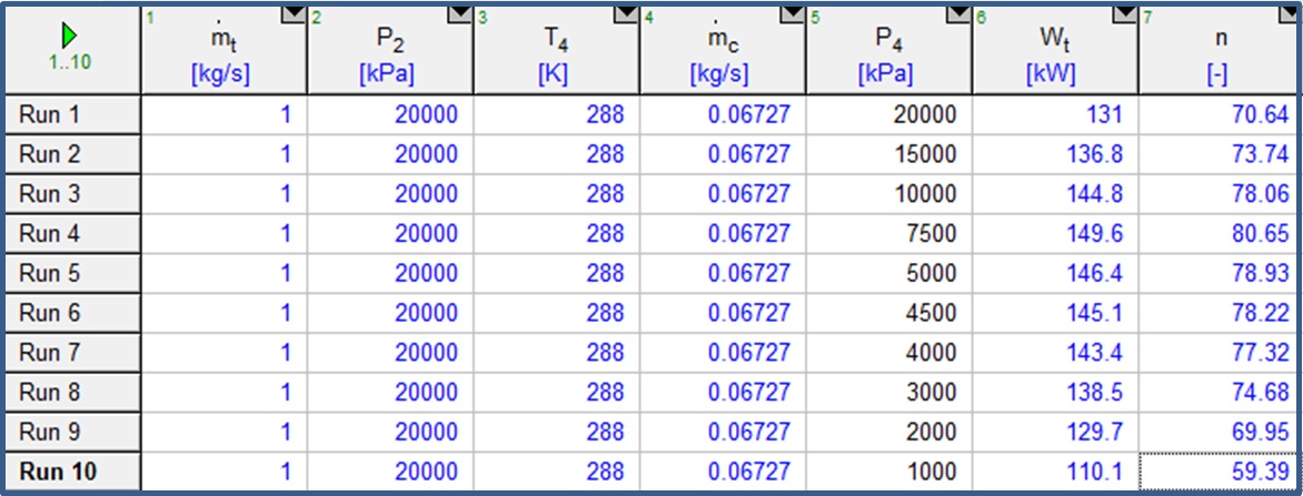
It was thought, based on usual gas turbine cycle background study, that a normal gas turbine would more likely operates at 10 bar. Therefore the work output from the turbine would be 110.1 kW, e.i. 99.09 kWe, which correspond in our case of a storage capacity of 1189.09 kWh of electrical output. The system efficiency is nearly 60%.
From the contact with the industry it was seen that the kind of compressor wanted would cost between £30,000 and £40,000. From this base, the cost of the system proposed was estimated to be £200,000.
Overall system
The system proposed is summarized below:
Performances
Capacity : 1189.09kWh (electrical output); 99.09 kWe for 12 hours
Efficiency : 59.39% in theory + CHP opportunity
Estimated price : £200,000
Components
2 Compressors
• 200 bars
• 31.55 kW rated power each
• Flow 58.9 SCFM (Standard Cubic Feet per Minute)which correspond to a 0.0278m 3/s each
• Water cooled
Storage tank
• 200 bars
• 185.3 m3 (15m long, 2m radius)
Expansion turbine for a pressure of 10 bar
Future Work
CAES systems are based on a mature technology but it was seen that a lot of practicality problems are found when trying to increase their efficiency and adapted them to small scale. The analysis run also comprises some uncertainties and assumptions. Therefore it was felt that further studies should be undertaken.
In order to provide a better model, more details about the system should be found and experimentation could be very useful. As CAES involve a lot of unstable process, it would be very valuable to be able to model in a dynamic way.