Corrosion and Biofouling
A monopile foundation is chosen for our structure. This structure is exposed to harsh sea conditions and must be able to endure such conditions for a period of 20-25 years. With the addition of tidal turbine, it is not only prone to corrosion but biofouling as well that can weaken the structure that ultimately reduce the efficiency of the turbine.
We look at some of the problems faced by the industry including pile spillage, internal corrosion, external corrosion and biofouling and their prevention methods.
Pile Spillage
Pile spillage is caused due to imperfectly grouted connections between the pile and transitional piece. One method of eliminating this problem is filling the piles from inside the tower with concreate up to the level where TP’s bottom section was embedded. Or by simply improving the traditional grout connection by welding shear keys inside the TP and outside the matching pile surface [1].
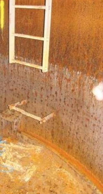
Internal Corrosion
For early projects only a corrosion allowance was added to the internal surface without any coating or protection system. It was assumed that the internal compartment was both water and air tight. But in practice this was found to be inadequate since it is not possible to have it completely air tight and sealed [2].
- Difference in the tide that resulted in the variation of the water level inside the pile [2].
- Micro-organism in the seawater that do not require oxygen to survive such as supher reducing bacteria (SRB) [1].
- Some suppliers insist on placing cables inside the tower going through pile and leaving the structure through hole below the water known as rat hole which is sealed. This seal has proven to be inadequate and allows water to enter the pile [1].
It has been suggested that coating the inside of the monopile with 200-250µm of epoxy zinc dust primer or adding a cathodic protection (CP) system. In some cases a combination of both can be used. Another method that is used is adding Impressed Current Cathodic Protection (ICCP) instead of CP. They provide the same level of protection (maybe elaborate on iccp difference from cp) [3].
External Corrosion
There are three section to the that need to be protected as part of the external surface:.
- Atmospheric Zone.
- Splash Zone.
- Immersed Zone (Sub Sea).
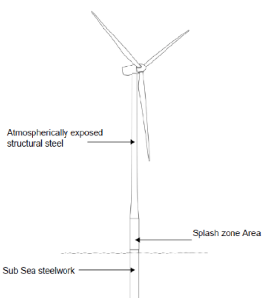
Atmospheric zone is the steel structure which is located above the sea water. This zone is highly corrosive due to high concentration of chlorides, long periods of wetness and UV light and therefore falls under the C5-M corrosion category according to ISO 12944-2 [5]. If left unprotected it can lead to corrosion of steel at the rate of 80-200 µm per year. It is recommended to apply no less than 3 coats of zinc-rich primer followed by epoxy intermediate coats and UV durable top coat (e.g epoxy siloxane) of minimum 320 µm dry film thickness (DFT) [6].
Splash zone is the area alternately above and below the water line. The corrosion rate is even higher in this zone and if left unprotected can lead to a corrosion rate of 200-500 µm. Unlike atmospheric zone it is also affected by additional stresses including erosion, debris and some cases ice. It is suggested using epoxy or polyester coating of more than 600 µm DFT. In order to increase the impact resistance in this area fibre reinforced coating are used and zinc-rich primers are avoided [6].
For the immersed zone it is recommended to use minimum of two coats of epoxy barrier coating of no less than 450 µm DFT [6].
The coating in external atmospheric and splash zone is compulsory whereas CP is mandatory for submerged zone and coating is optional in this zone as is intended to reduce the required CP capacity [2]. It is important that the CP system is compactable with the epoxy coasting system used [6].
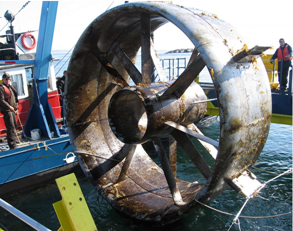
Biofouling
With the addition of tidal turbines and tidal turbine support structure to our monopile biofouling becomes a major issue and needs to be addressed.Marine biofouling in simple terms can be defined as accumulation of undesirable microorganism, algae and animals on the surface of structure submerged underwater It increases the drag resistance of tidal turbine blades and increases the weight of the structure which ultimately leads to loss of efficiency of the system [6].
There are two types of protection that can be used such as non-stick, fouling release coating or chemically active antifouling paints coating to protect the structure and ensure efficient working [6].
- Wind power offshore (2017). Foundations built on corrosion protection. [online] Available at: http://www.windpoweroffshore.com/article/1314301/foundations-built-corrosion-protection [Accessed 6 May 2017].
- Corrosion protection of offshore wind foundations (2015). Force Technology.
- Materials performance (2017). Corrosion Risks and Mitigation Strategies for Offshore Wind Turbine Foundations. [online] Available at: http://www.materialsperformance.com/articles/material-selection-design/2016/03/corrosion-risks-and-mitigation-strategies-for-offshore-wind-turbine-foundations [Accessed 6 May 2017].
- Galvinfo(2017). Available at: http://www.galvinfo.com/Thermal_Spraying/cp_os_wind_apps.html [Accessed 6 May 2017].
- By Anders Voldsgaard Clausen, H. (2017). Tips for Offshore Wind Corrosion Protection. Renewable energy world. Available at: http://www.renewableenergyworld.com/articles/print/special-supplement-wind-technology/volume-2/issue-4/wind-power/tips-for-offshore-corrosion-protection.html [Accessed 6 May 2017].
- Marine Fouling and Corrosion Protection for Off-Shore Ocean Energy Setups. (2010). ICOE.
- Racerocks(2017). Tidal Power Project Fouling at 6 months. Available at: http://www.racerocks.com/racerock/energy/tidalenergy/april07fouling/fouling.htm [Accessed 6 May 2017].