Methodology for a Decision Support Tool for a Tidal Stream Device
MSc Sustainable Engineering: Offshore Renewable Energy


Material Analysis Tool
The motivation behind the development of this tool was to investigate the damage to the blade integrity caused by the impact of the varying loading profile acting on the turbine. Within the timeframe available it was considered that a Damage Equivalent Load (DEL) method would allow an insight into the performance of a particular blade material in these extreme conditions.
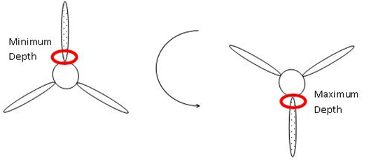
The cyclic nature of the turbine rotation means that within a few seconds the loading on the turbine can vary significantly over the profile of the blade. This is the primary driving factor in the decision to restrict the location of the turbine to allow a flow variance of 5-15% over the total profile of the rotor. However the effectiveness of this design restriction must be evaluated and a measure of damage accumulation over the design life of the blade estimated.
The aims of the tool were to:
Quantify the effect of the calculated loading profile on the design life of the rotor
This analysis was focused on the blade root area because the loading profile acting on the root is critical for designDownload: Material Analysis Tool
Inputs
The names in bold correspond to the title in the relevant excel source.
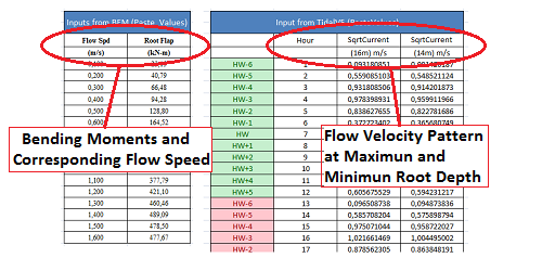
As highlighted in the BEM section, the hydrofoil of the turbine is split into distinct segments. For the segment of interest the variation in flapwise bending moments over the range of incident flow speeds is required for analysis. In this instance the area of interest is the blade root, this is also the salient loading characteristic for blade design. Therefore from the outputs of the BEM simulation tool the inputs required are:
• The range of flow speeds (Flow Spd)
• The corresponding root flapwise bending moments (Root Flap)
• Rotational speed of the turbine rotor
From the Tidal Resource tool the following information is required:
• Flow pattern at the both the maximum & minimum depth of segment as it rotates (SqrtCurrent *factor) over 360 h.
This tool also requires data regarding the SN curve and yield strength of the materials for analysis. This information is namely the equation of the line of the selected material of the SN curve. The equation of the line is of the form:
SN Curve
Where S stress amplitude, Nf is number of cycles to failure, A is a constant and B is the slope of the SN curve (sometimes denoted as (-1/m). This information can be gathered from a range of sources depending on the nature of the material . Alternatively this information can be assembled through industry contacts with blade material manufacturers or existing professional knowledge.
Additionally the following inputs are required which are user specified:
• Stress safety factor
• Required design life
• Geometry of root segment
Material analysis Tool Inputs
Outputs
The outputs from the tool are for the specific segment under analysis. In this case it will be for the blade root; however the tool could be enhanced to be capable of analysing the hydrofoil structure:
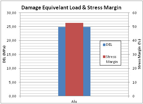
• Damage Equivalent Load (DEL) value over operation
• Stress margin of Damage Equivalent Loads versus the stress range to failure to evaluate the effect of damage
accumulation.
Material analysis Tool Outputs
Methodology
From the blade root bending moment data set entered from HARP_OPT the axial stress can be computed from the following method obtained from which gives the resulting root axial stress corresponding to a particular flow speed. The thickness and diameter of the root:
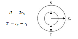
Thickness and diameter of the root
For this geometry the moment of inertia and the axial stress are:
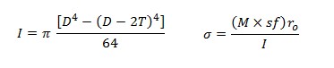
Moment of Inertia and the Axial Stress
Where:
• ‘M’ is the root flapwise bending moment for a particular flow speed
• ‘sf’ is the stress safety factor
This axial stress, calculated from output data from the BEM tool, is then related to the two corresponding flow speed profiles, at the maximum and minimum depth of the segment, every hour for 360 hours from the Tidal Resource tool which can be extrapolated. This stress range gives an idea of the stress variation experienced by the root in each rotation of the blade.
Stress variation
At each sea state (HW, HW+1 etc.) it was then assumed that within this timeframe the stress experienced by the blade root occurs at constant amplitude between the axial stresses at the maximum and minimum depth of the root as it rotates. The number of cycles at every available sea state is then counted over the period of 360 hours and extrapolated to the user-specified design life. Essentially this method splits the loading cycle into certain stress range 'bins' which occurs over the duration of the analysis.
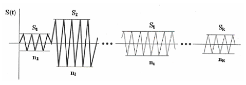
Spectrum of Constant Stress Amplitude
To evaluate the damage these loading cycles exert on the blade these stress ranges are used to generate the Damage Equivalent Load (DEL). This equates the damage by a spectrum of cyclic stress amplitudes to that of a single frequency (1 rotation of the blade) over the design life of the design:
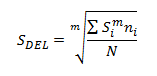
Damage Equivalent Load
Where:
• m is from the SN curve equation: (-1/B)
• Si is the stress amplitude ‘bin’ and n_i is the number of cycles at the stress range bin
• N is the number of cycles in the user-defined design life
This Damage Equivalent Load value can then be compared to stress range that leads to failure for the specified design life (S_f), which can be calculated from the SN curve data and the rotational speed of the turbine. This gives the stress margin which is essentially a safety margin during operation:
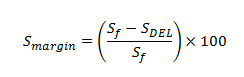
Sstress safety margin during operation
Where the design of the turbine blade is operating within safe limits at positive values and the design of the turbine blade segment is driven by damage accumulation as the margin approaches zero or reaches negative values.
References:
➙ [24] Herbert J. Sutherland. A Summary of the Fatigue Properties of Wind Turbine Materials. Wind Energy. January 2000.
➙ [25] Boyer, Howard E. Atlas of fatigue curves. ASM International, 1986.
➙ [26] Total Materia The world’s most comprehensive materials database. May 2014.
➙ [27] Montana State University Composite Technologies Research Group May 2014.
➙ [28] G.N McCann. Tidal current Fatigue Loading Sensitivity to Waves and Turbulence. Proc. European Wave and Tidal
Energy Conference. 2007.
➙ [29] ARIDURU, Seçil. Fatigue Life Calculation by rainflow cycle counting method. M.S. Thesis, Department of
Mechanical Engineering. MIDDLE EAST TECHNICAL UNIVERSITY. December 2004.
➙ [30] Graeme McCann. Implications of Site-Specific Conditions on the Prediction of Loading and Power Performance of
a Tidal Stream Device. Conference Proc. Ocean Energy (ICOE). 2008.