Small Scale Hydro: Novel Approaches to Generation & Transmission

Tunnel Modelling
Defining the model:
As part of the consideration for the transmission we decided to put together a computational fluid dynamic (CFD) analysis of the flow of water past a simple obtrusion designed to represent a small fixing to the cable that may be required to keep it in palace. We hoped this would provide information to understand any stresses the cable, or any fixing, may come under so as to better understand any repair and maintenance that would be required, as this would be vital in justifying such an unusual method of transmission in a rather confined area.
Given the previously discussed cable specifications, modelling of potential tunnel anchor block was carried out. It was decided the obtrusion it-self would be 1.5 times the diameter of the cable high by 2 times the diameter deep spanning the full width of the tunnel as shown in the initial auto-cad image below. Once this was decided the tunnel was modelled to be 3 times the diameter of the pipe upstream of the obtrusion and 5 times the diameter of the pipe downstream so as to allow for settling of any turbulent regions.
The intention was then to analyse the pressures on the cable and the velocity of the water. Above 3ms-1 is where erosion from particles in the water becomes a consideration. Below this, corrosion is the main effect, however this is the case in a saline marine environment, but in freshwater situations, there is less salt, hence less chlorides and less corrosion potential of the reinforced concrete.
Method:
It was decided that initially a 2-D model should be put together to gain an understanding of the outline of the model and how best to exploit the relevant applications involved in developing the model so as to obtain any useful data.
2-Dimensional Analysis of Fixing and Cable in Supply Tunnel.
A simple cross-sectional model of the supply pipe, cable and obtrusion were put together using Gambit. After discussions amongst ourselves and through enquiry to Scottish and Southern Energy, the supply pipe owners, it was decided to model the supply pipe at 2m. This also allowed for modelling of the obtrusion under a worst case scenario flow.
The model was set to run 3 times the diameter of the pipe upstream of the obtrusion and 5 diameters downstream so as to allow an appropriate distance for the flow to settle.
Volumetric flow data was initially calculated using LowFlows, then, using the Colebrook-White equation, velocity of the water was calculated to be 1.5ms-1
Using the following equations, turbulent kinetic energy, k, and turbulent dissipation rate, e, were estimated based on initial velocity from previously calculated data.
- k=0.010125
- e= 0.07908
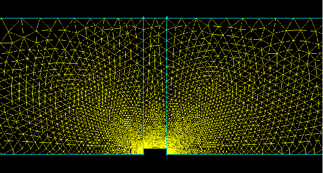
Once completed the following pressure and velocity results were obtained where the colour indicates a specific velocity or pressure corresponding to the gradient bar next to it. No further data was obtained from the 2-D model as the complex three dimensional currents and eddies that would occur could not be properly accounted for in two dimensions.
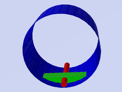
Further Fluent Work Required:
We believe further modelling in 3-D could be carried out in order to obtain accurate flow data. While it would be very difficult to get a precise model without experiments to compare results it would provide a good starting point to understand any stresses and strains that cable and fixings may come under. A suggestion of what this model may look like can be seen below.Discussion around the economic side of the transmission options can be found here .