Small Scale Hydro: Novel Approaches to Generation & Transmission

Pipe Network
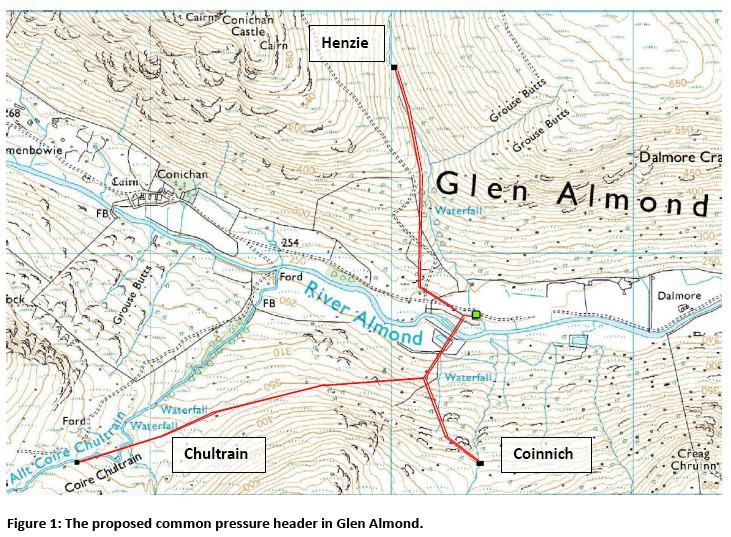
In order to find if a common pressure header configuration (Figure 1) is advisable for a particular scheme, we first had to ascertain the potential hydraulic losses that may be caused due to pipe junctions and the effects of varying head loss.
Published by the Engineering Sciences Data Unit (ESDU), the paper titled Pressure Losses in 3 Leg Junctions: Combining Flows (ESDU 73023) [1] details the equations used to calculate the pressure losses that are incurred when two pipes, both running full, are joined at an angle to form one flow. This document formed the basis for evaluating the potential head losses that were likely to occur should the water courses of Henzie, Chultrain and Coinnich (Figure 1) be combined to a common pressure header.
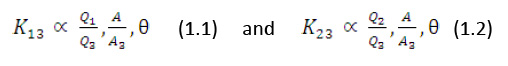
In order to conduct analysis on any hypothetical pipe networks, it was assumed that all joins would be 45° Y-junctions as this would be most representative of the layout of the scheme. The loss coefficient K of a junction combining feeder pipes 1 and 2 to a larger main pipe, 3, is dependent on the ratio of inflows to outflows, the area ratio and the angle (1.1 and 1.2).
Therefore, having considered the potential flow ratios that occur when combining Coinnich with Chultrain and then Coinnich/Chultrain with Henzie, the K value (and hence head loss) that would occur with a 45° Y-junction was considered suitable for the site.
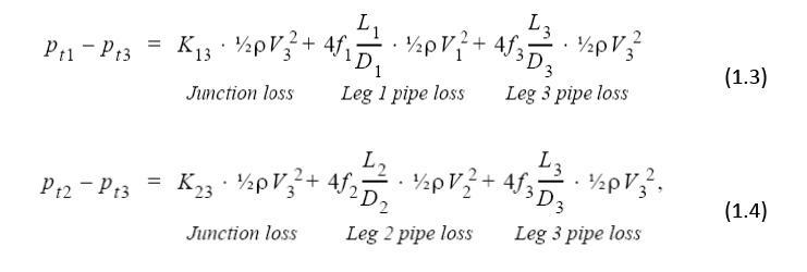
The total pressure losses across pairs of inlet and outlet legs of a junction are:
Where:
- Pt = total pressure (N/m2)
- K= Total pressure loss coefficient
- ρ = fluid density (kg/m3)
- V= mean flow velocity (m/s)
- f= fanning friction factor
- L = pipe leg length from junction (m)
- D = Pipe diameter (m)
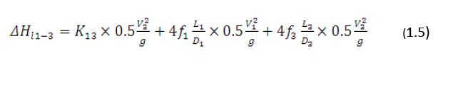
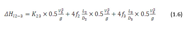
Hence, the total head losses across pairs of inlet and outlet legs of a junction are calculated from equations (1.5) and (1.6), where Hl1-Hl3 and Hl2-Hl3 are the respective head losses
Where:
The head losses can be reduced when the corners of the junction are rounded, therefore to evaluate the most extreme losses likely to occur the joins are considered to be sharp cornered, therefore K13=K13’
- ΔHl = Head loss incurred in the junction (m)
- g = acceleration due to gravity (m/s2)
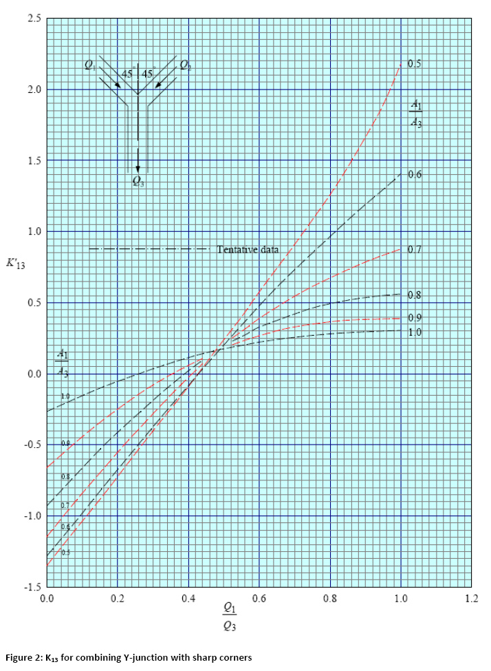
Assuming a join angle of 45°, the values of the loss coefficients K13 and K23 are obtained from Figure 2:
Conclusion
Taking the maximum flow likely to occur and estimating the likely pipe diameters for Coinnich, Chultrain and Henzie, the loss coefficients K were found to be in the region of 0.2 to 0.4.
As the contribution to head loss from a pipe join is:
The maximum head loss likely to occur was calculated to be less than 1m for our given flow characteristics, which is less than 1% of total head. As this 1% head loss will occur when the flow velocity reaches maximum levels i.e. greater than 10m/s, it was assumed to be negligible, as flow velocities in the region of 10m/s are the least probable from the flow duration data for the corries. In addition, as the pipe diameters under consideration are less than 1m, a flow velocity greater than 10m/s is unlikely to occur as frictional effects are still dominant.
Ref [1] - ESDU work Sheet 73023
As the energy captured by the various types of system can now be modelled, the economics involved can also be integrated into the analysis. Details of this can be found here.