Heat Pumps
Heat pump (HP) is a technology used for decades around the world. These devices transfer heat from one place to another; a common example is a refrigerator or an air-conditioning unit. A heat pump has different components depending on the refrigeration cycle it uses. Two practically used refrigeration cycles exist – compression cycle and absorption cycle. The first is more energy demanding as the compressor generally consumes more energy than a pump which is used in the absorption cycle. Simple graphic comparison of the cycles is provided in the figure bellow.
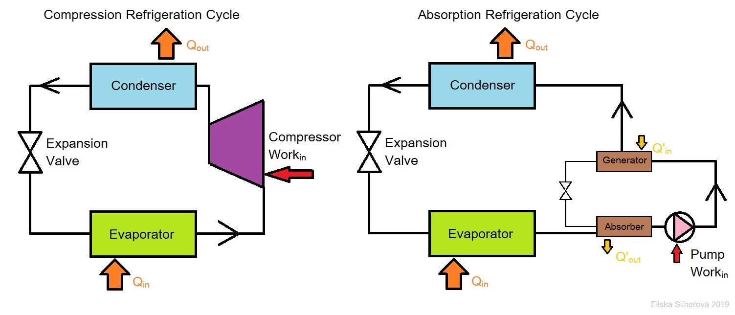
A simple schematics of the compression (left) and absorption (right) refrigeration cycles [i]
Large scale heat pumps[a] (LSHP) have been used for DH applications from the early 1980’s. The country to introduce these systems in Europe was Sweden to balance off its surplus of electricity produced by its, at the time, newly opened nuclear power plants. The LSHPs currently in use within EU are mainly water-sourced using different water available as well as various different refrigerants. Around 24% of these use ambient water, where supply water temperature usually ranges between 2-15°C. The two main refrigerant types are natural (ammonia and CO2 ) and synthetic (hydrofluorocarbons (HFCs)).[1] The first heat pumps (HP) schemes uses HFCs, and the refrigerant needs to be changed/HP phased out by the 2040 as it was discovered, that the HFCs are harmful to the ozone layer.[2]
The efficiency of the HP is given by the coefficient of performance (COP) which is the ratio between thermal output and electricity input. The highlight of a HP DH scheme is the efficiency compared to other usual DH technologies (boilers, CHPs etc.). Common COP of LSHP schemes operating in Europe is between 3 and 4. Generally, the lower the temperature lift[b] is, the higher the COP will be.[3]
In the time of climate emergency and the urgent need of deploying more renewable energy schemes as well as decarbonising the heat production the LSHP can work as a balancing mechanism to the electricity grid as well as supply of clean heat. The LSHP were shown to be an important part of the Smart Energy Systems, as LSHPs enable for easier and efficient integration of fluctuating electricity supply for the wind farms and photovoltaic (PV) panels, especially when the DH system has a thermal storage where the HP can dump the excess heat and store it there.[4] [5]

The size of the HP depends on the demand of the DH system. If the HP is retrofitted to an existing DH scheme, the sizing is simple as measured heat consumption data exist. For new systems the demand is estimated and it is common to overestimate the heat demand and therefore oversize the system. If future extension of the DH network is planned the HP should be scaled accordingly as the lifespan of the LSHP may be more 40 years.[1] Regardless of the fact that the water source (WS) HP returns the same amount of water it takes from the river; in the UK the usage of WSHP is regulated under the abstraction licence.
There is clearly need for a back-up systems in case the HP would need maintenance or help covering the peak demand. The thermal storage can act like a short term back-up as well as cover the peak demand. A direct electric heat injection (DHI) should be included within the thermal store serving as a long term back-up. In cold climates such as Scotland, where the temperatures of the source water are below 4°C, the system should integrate a pre-heater to avoid freezing in the heat exchanger of the HP.

- Capacity above 1MWth
- The amount of difference between the source temperature and the temperature supplying the DH