• Home
  • OVERVIEW
    • Motivation
    • Policy
    • District Energy
    • Main heat source selection
    • Case study: Kinlochleven
    • Methodology
  • THE PROJECT
    • Heat Demand Assessment
    • Network Modelling
    • Network Design
    • Assessment of potential renewable sources
    • Environmental Impact
    • Financial Assessment
  • CONCLUSIONS
    • Final review
    • Sensitivity Analysis
    • Further Work
  • RESOURCE CENTER
    • Acknowledgements
    • References
    • Downloads
  • THE TEAM
  • Home
  • OVERVIEW
    • Motivation
    • Policy
    • District Energy
    • Main heat source selection
    • Case study: Kinlochleven
    • Methodology
  • THE PROJECT
    • Heat Demand Assessment
    • Network Modelling
    • Network Design
    • Assessment of potential renewable sources
    • Environmental Impact
    • Financial Assessment
  • CONCLUSIONS
    • Final review
    • Sensitivity Analysis
    • Further Work
  • RESOURCE CENTER
    • Acknowledgements
    • References
    • Downloads
  • THE TEAM

Network Design

One of the first considerations concerning the network design was the architecture of the village and the existing village layout. The pictures below represent the current layout of the village. Autodesk AutoCAD software was used in order to design the proposed district energy network.
Picture
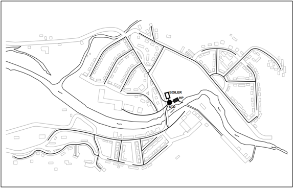
Kinlochleven layout. Source: Google Maps
Picture
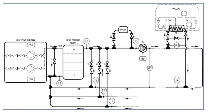
Proposed district energy network layout
The village is mainly consisted of three parts: a) one part of the village is located below river Leven, b) another part of the village is located in the upper left part upon the river and c) the last part is located in the upper right part upon the river.
 
The most viable solution for the district scheme was decided to have one main water source heat pump, one storage tank and one auxiliary boiler that will be located in the middle of the village to distribute with the most efficient way the heat required.
Once the main and auxiliary heat sources and storage have been defined, the next step will be to design the following components:
  • Piping Network Design
  • Heat Interface Units (HIU)
  • Centrifugal Pumps
​Pipe Network Design
The design of the network is dependent on many factors. Those factors regard the following aspects:
  1. Road Layout
  2. Houses Arrangement
  3. Site Particularities
  4. Heat Source
The network design can have three different layouts: a) radial form, b) meshed form and c) ring form. All those types are presented in the pictures below.

Picture
Picture
Picture
Layout options for network design: Radial, Meshed and Ring Network (from left to right)
Considering the topography of the village and the reasons above we concluded that the radial type of network was the most feasible one.
 
The network is composed by three main branches. The most heat demanding receptor is the school, so it is supplied by a different branch so as to cover the peak load at all times. The second branch covers the heat demand of the village below the river and the third branch covers the heat demand upon the river.
 
Materials
The materials of the piping for District Heating Schemes are mainly pre-insulated pipes. The pipes are comprised of three main components:
  1. Outer jacket
  2. Insulation
  3. Carrier pipe
Picture
                                                                                      Cross-Section of a pipe Source: Rehau
 
The outer jacket improves the flexibility, the structural properties and prevents bending.
The role of insulation is to reduce the heat losses and maintain the temperature difference across the network. The material of insulation is polyurethane (PU) or cross-linked polyethylene (PE).
The carrier pipes have two different options of material either steel or cross-linked polyethylene. Also, in PE-X pipes the flow and return pipes can exist in the one jacket. The pictures below represent those different choices.
Picture
Picture
Picture
Pipe material options: steel pipe with PU foam, polymer pipe with PU foam, polymer pipe with PEX foam. Source: REHAU
Calculations
The calculation of the heat demand had defined the capacity of the water source heat pump, which is calculated to be of 1.2 MW. Also, the district energy scheme project aims to implement a 4th generation network. This in turn means that the flow and return temperatures will be 60°C and 40°C respectively. The pressure drop and the velocities were established at 250 Pa/m and 1.5 m/s respectively. Those assumptions were decided after having considered the CIBSE Guide C and Rehau suggestions. The assumptions and the 4th generation district heating data are presented in the following table.
Picture
Pipe sizing assumptions
Depending on the number of dwellings different diversity factors were applied for both domestic hot water and space heating.
Picture
Diversity factors as a factor of number of dwellings
After applying the diversity factors the velocity of the fluid, the mas flow rate, the pipe diameter and the heat losses were calculated.
​The following equations were used to define these parameters with the Moody chart.
Picture
​​Two case scenarios had been developed at this stage. The first case scenario considered that each house had an accumulator tank and the second one considered instant heat exchangers without accumulator tank. In the first case the instantaneous heat load does not exceed 6 KW, whereas in the second case scenario the threshold is 35 KW. Therefore, the pipe diameter, the pressure drops and the velocities differ according to these cases.

The next step was the calculation of the heat losses. The pipe layout is presented in the following picture.
Picture
Pipe cross section   Source:http://www.cheresources.com/content/articles/heat-transfer/making-decisions-with-insulation?pg=3
​The equations used to calculate the heat losses are the following:​
Picture
​The annual heat losses were calculated and accounted to be 11% of the annual heat demand. The following pictures represent a part of the calculations that were performed taking into account the above equations, so as the main parameters of the system were calculated.
Picture
Example of part of the calculations without accumulator tank
A graphical representation of the above results on the network map can be seen in the following image.
Picture
Network design
Important considerations
​

 1. Water quality standards
For the water flowing inside the pipes, the following quality standards have to be considered according to BS 2486:1997:
  • pH 9-10
  • Alkalinity < 60 mg HCO3/l (mg/l)
  • Oxygen level < 20 μg/kg
  • Total Fe < 0.1 mg/kg
  • Total Chloride < 50 Cl mg/l
  • Total hardness < 0.1 dH
​
2. Legionella risk
​​Legionella is a bacterium that can easily develop and reproduce in wet systems. In the case of systems with individual water tanks in each dwelling, the control and monitoring of the water temperature in the domestic tanks is mandatory. A fourth generation district energy network usually operates at 60°C – 40°C, meaning that a regular pasteurization is required periodically, so as to prevent from bacteria growth. The temperature should be increased close to 60 °C, so that the bacteria are killed in less than 30 minutes as it can be seen in the following graph.
Picture
Legionella growth at different temperatures. Source: London Heat Network Manual
3. Heat Linear Density
In the pre-feasibility stages of the development of district energy schemes, the linear heat density is an important factor as it is an indicator of the network losses. As it can be observed from the figure below, as the linear heat density rises the annual heat losses are reduced.
Picture
Losses as a function of the heat density for different European countries. Source: Swiss Federal Office of Energy 
Picture
​Therefore, this means that the expected annual heat losses according to the average of five different European countries for the current case study is 16.7 %. It should be noted that these data refer to earlier generations of district energy networks with higher losses than 4th generation networks. This in turn means that the losses should be further investigated to evaluate the worthiness of a district scheme implementation.
Heat exchangers
In district energy networks, the plate and frame heat exchangers or flat plate heat exchangers are commonly used, due to their higher heat-transfer coefficients, compact size, cost-effectiveness and unique ability to handle fouling fluids. Plate heat exchangers also make it easier to adjust heat transfer capabilities, as they only require the adding or removing of plates.
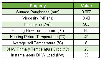
To size the heat exchangers our Team had to consider both the space heating and the domestic hot water demand. Based on common practice, this means that each dwelling has an instantaneously total heat demand of 35 kW on average. 
Picture
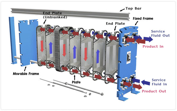
Plate and frame heat exchangers. Source: Iklimnet.com
Centrifugal Pumps
​A centrifugal pump was estimated in order to supply energy to the fluid in each branch of the district heating network. The standard equation to estimate the hydraulic power is shown below:
Picture
​Where:
P = Hydraulic Power transmitted to the fluid by the pump in HP.
Q = Flow in m3/h.
η = Efficiency of the pump.
H = NPSHa.

Net Positive Suction Head (NPSH) concept
NPSHr = head required @ the eye of the pump's impeller to prevent cavitation, a function of pump design.
NPSHa = head available from the suction side of the system, must always equal or exceed the required (NPSHr) to prevent cavitation.

​NPSHa Factors considered:
Positive 
  1. Absolute pressure on liquid       
  2. Static suction head         
Negative
  1. Vapour pressure of the liquid, absolute
  2. Friction & entrance losses
  3. Static suction lift
 
The main characteristic curves of the centrifugal pumps chosen are:
Picture
Characteristic curves of the pump. Source: Sulzer
​For the electrical power it was required to include the power factor, which was estimated in 0.8. Thus, the final electrical power of each pump was 7.5 HP. 
Control and Monitoring
​The control systems play a significant role in the operation of the network. Control components should be placed in every branch of the network in order to maintain a desirable level of comfort at any time. Also, the importance of the control systems had to do with the monitoring at different places of the network. The components that have been used for the network are pressure difference sensors and temperature sensors. These sensors are placed in critical points of the network, in order not only to maintain the flow rate at desirable levels but also introduce potential points of failure such as leaks or cracks. In the following picture the different components are presented along with the sensors for one branch of the network.
Picture
Components of the system and control
​Depending on the temperature and pressure readings, the operation of the heat pump, auxiliary boiler and centrifugal pumps changes, increasing or decreasing the water flow or switching on or off the heat sources. An example of this type of operation controls can be seen in the following picture.
Picture
Flow Chart of the system
Create a free web site with Weebly