ESP-r: Summery of Simulation Entities

The data model is embedded within the source code of ESP-r. Header files define parameters determining the size of the data structures. There are alternative header files to support smaller models and/or constrained computing platforms, medium scale models as well as larger projects.

The evolution of the data model also tends to involve changes to model files (see below) as well as the source code. With few exceptions data structures are documented within the source code, primarily where they are read from file or within the source header files.

In general, older model files (up to roughly a decade old) can be read and used with little or no user intervention. There are facilities to upgrade model files, usually with little or no user intervention.

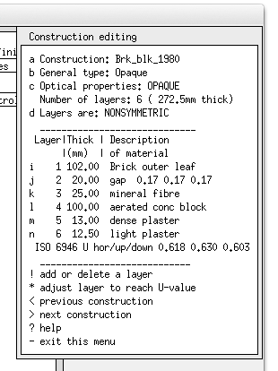
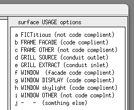
The ESP-r data model is a super-set of that used by conventional CAD tools. It also includes visual entities used by Radiance, acoustic attributes, life-cycle attributes, as well as unused optical attributes from imports of optical data. Each entity has a set of attributes and supports a specific set of thermophysical interactions.

The following types of entities are included:

  • calendars ESP-r maintains a julian calendar and user defined day types .e. summer_weekday associated with specific calendar days). Environmental control and casual gains schedules are based on day types (details).
  • conversions from primary energy Heating, cooling and small power demands are paired with conversion factors to primary energy as well as power plant pollutants.
  • site A latitude and longitude as well as a set of sky and ground exposures and wind exposure are held (details).
  • land forms and adjacent buildings are made from ground surface sets, solar obstructions or visual entities. Each has a name, composition and form.
  • thermal zones are enclosed air or water filled volumes which must conform to a set of syntax rules. In terms of its semantics, scale and complexity a thermal zone can represent anything from a thermostat case to a floor of a building (details).
  • furniture and internal mass are represented as surfaces within zones. If included they fully participate in the zone solution (details).
  • surfaces are polygons of arbitrary complexity with associated attributes and which follow a set of syntax and topology rules (details).
  • composition materials (details) and constructions (details) are held in common or project based databases and when selected become named attributes of geometric entities in the model. Prior to use by the simulator the underlying numerical attributes will be extracted and placed in model files for quick access.
  • constuction layers
  • intended use or code compliance criteria some model and zone and surface attributes can be used to support compliance tasks e.g. surfaces may be marked as code compliant so that automated replacements can be carried out.
  • surface USE
  • topology surfaces include attributes to specify what happens on the other side (see below). Some, such as similar to current are useful approximations for adjacent spaces that are likely to be at the same temperature as the current zone.
  • surface USE
  • environmental control logic can be defined via ideal controls or component based components. Both approaches include specific definitions of sensors (what is sensed, sensor location see figure below), a schedule of control laws (PID, ON-OFF, multi-stage) and actuator (where heat is injected or extracted). Ideal approaches can be used to characterise demand patterns with control logic prior to investing in attributing networks of detailed components.
  • environmental controls sensor choices
  • environmental system components have initial descriptions drawn from a database (details) and linked (by the user) to form a network description (see below). Components can have controls imposed as required and associated with specific thermal zones.
  • environmental controls
  • a list of air-side-components can be found (here).
  • a list of heat exchangers and coils can be found (here).
  • a list of thermostats can be found (here).
  • a list of boilers can be found (here).
  • a list of water-side components can be found (here).
  • a list of heat pumps can be found (here).
  • a list of accumulators can be found (here).
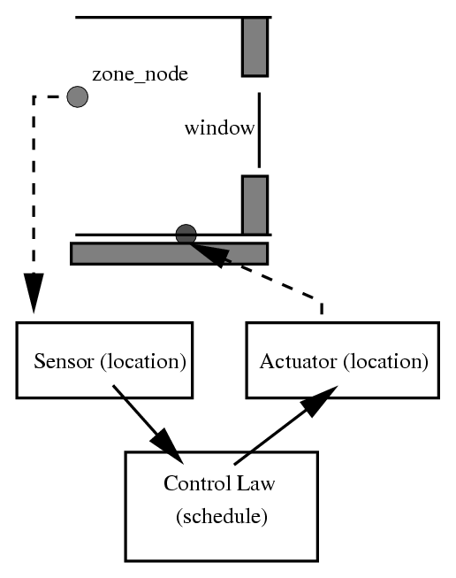
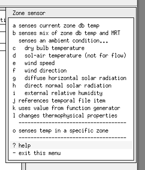
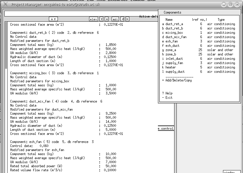
  • As components are selected for use the user updates the component attributes for the specifics of the network in the model. The user then specifies the nodes in associated sending components to complete the network description.


  • power generation and distribution are represented by combinations of additional attributes to casual gains associated with networks of electrical distribution devices.
  • environmental controls
  • imposed (scheduled) air are defined as schedules of infiltration and ventilation from other zones with the option of some basic control (e.g. increase infiltration in high wind speeds or if room goes above a setpoint). Useful for early stage what-if questions.
  • calculated air and fluid flows are based on nodes (zones and boundary points), components (openings, fans) and linkages with optional control applied.
  • Bruntland network
  • casual gains are defined as schedules of sensible and latent gains associated with specific day types and typically representing occupants, lighting, small power loads - the latter might include AC or DC power attributes. The figure below shows gains associated with an examination room where Thursdays are different than other weekdays.
  • casual schedules

    Summery of model files

    ESP-r models are held in a distributed folder structure with different entity types in different files (see below).

    text mode invocation

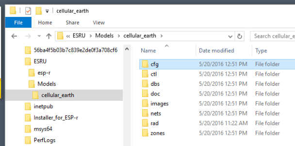
    Inside each of the folders are topic-specific model files. Below are the files for one of the simple exemplar models. The functionality-follows-description of ESP-r created new files as the user evolves a model. File name extensions give a clue as to the topic. In the case below an explicit zonal representation of an earth tempering conduit has resulted in additional files - .htc are heat transfer coefficient directives for those zones.

    cellular_earth
    --- cfg
        --- cellular_earth.cfg - the model cfg file
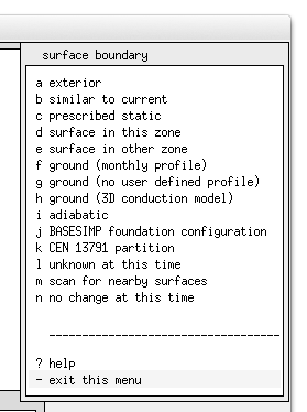
        --- cellular_earth.cnn - the master list of surface boundary conditions
    --- ctl
        --- cellular_earth.ctl - environmental control definitions
    --- dbs
        --- multicon.db5       - model-specific construction database
    --- doc
        --- cellular_earth.log - user notes about the model
        --- cellular_earth_db5.contents - the QA report about the model
    --- images                 - images associated with the model
        --- earth_tube.fig
        --- earth_tube.gif
        --- earth_tube_temp_mod.gif
        --- layout_of_earth_tube.gif
        --- spring_earth_tube_perf.gif
        --- summer_earth_tube_cool.gif
    --- nets                   - network definition folder
        --- cellular_earth.afn - mass flow network
    --- rad                    - Radiance files (none for this model)
        zones
        --- corridor.con       - thermophysical properties
        --- corridor.geo       - geometry and attribution
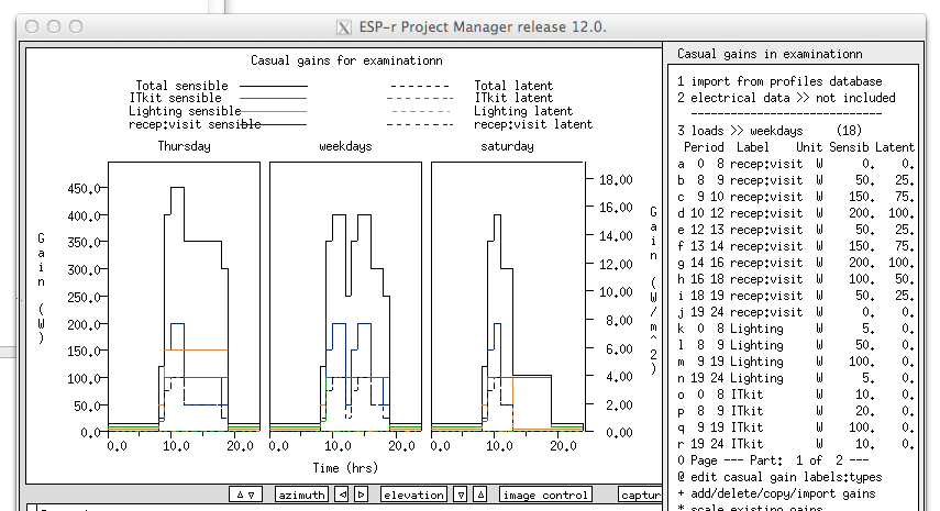
        --- corridor.opr       - casual gains & scheduled infiltration
        --- corridor.tmc       - optical properties
        --- manager.con
        --- manager.geo
        --- manager.obs
        --- manager.opr
        --- manager_a.con
        --- manager_a.geo
        --- manager_a.obs
        --- manager_a.tmc
        --- manager_b.con
        --- manager_b.geo
        --- manager_b.opr
        --- manager_b.tmc
        --- tube_a.con     
        --- tube_a.geo
        --- tube_a.htc     - heat transfer coefficients
        --- tube_a.opr
        --- tube_b.con
        --- tube_b.geo
        --- tube_b.htc     - heat transfer coefficients
        --- tube_b.opr
        --- tube_c.con
        --- tube_c.geo
        --- tube_c.htc     - heat transfer coefficients
    

    Most model files are ASCII text and follow a tag:data format (a few files include position-specific formatting).

    FILE EXAMPLES TO BE ADDED HERE
    

    Back to top | Back to Welcome page
    ©Copyright 2017 Energy Systems Research Unit, Glasgow, Scotland. License: GPL V2. Last edited by JWH, 20 Mar 2017