Environmental System Network Components
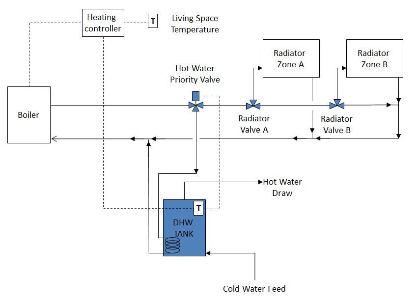
Component based environmental control networks are built up from entities in the systems components database. As each component is selected the user can alter its attributes to reflect the requirements of the current network. Each component is linked linked to one or more nodes in an up-stream component. Subsequently control logic may be associated with the component. For example, a typical layout for a boiler which would need to be translated into a system network description is shown below:
 see full size
Database entities
ESP-r includes a database of environmental system components from which environmental system networks can be built. The entities in the database hold the definition of the control volumes (nodes at which an energy balance and optionally, where first and second phase mass balances are maintained), the matrix layout, the initial component attributes as well as the types of derived performance data to be exported.
As components are selected for use the user updates the component attributes for the specifics of the network in the model. The user then specifies the nodes in sending components to complete the network description.
Within the code, each component type is matched to subroutines which decode the attributes and matrix layout and generate the matrix coefficients for the solver.
The components included with ESP-r represent a variety of approaches to how components are represented, their thermophysical resolution and the level(s) of control which can be implied. There are thus multiple radiators, boilers and accumulators to choose from. Some components are represented as a single control volume while others may have more than a dozen. The number of attributes ranges from 4-132. Some components also include data for associated mass flow entities.
The following tables provide a summary of current system components. The columns are:
Air-side Components
Air side components are listed in the table below with a summary of attributes and indicators of the level of resolution.
| Name | Nodes | Connections | Attributes | Derived outputs | Flow type |
|---|---|---|---|---|---|
| centrifugal fan with flow control | 1 EB+MB | 1 dry/moist air | static rated absorbed power, mass flow rate, efficiency plus timestep mass flow rate | real & reactive power & internal heat generation | general flow inducer |
| AC fan with submerged motor | 5 (EB+MB @ 2 solids & 3 dry/moist air) | 3 (dry/moist air) | motor & casing mass, surface areas, specific heat, rated flow rate & power & velocity, efficiency plus timestep flow rate | none | none |
| air (dry & moist) flow multiplier | 1 EB+MB | 1 (dry/moist air) | 2 flow ratios | none | none |
| air mixing box or converging junction | 1 EB+MB | 2 (dry/moist air) | 3 | none | general flow conduit |
| air duct | 1 EB+MB | 1 (dry/moist air) | hydraulic diameter, length, x-section area | none | general flow conduit |
| insulated air duct | 4 EB+MB @ 2 solids & 2 dry/moist air | 2 dry/moist air | layer mass, specific heat, thermal resistance at each face, heat transfer area, effectuve duct diameter, length, typical velocity | none | none |
| air duct damper with flow ratio control | 1 EB+MB | 1 dry/moist air | timestep flow fraction | none | general flow corrector |
| air flow diverger | 3 EB+MB @ dry/moist air | 3 dry/moist air | 1 flow ratio | none | none |
| air flow converger | 1 EB+MB | 2 dry/moist air | none | none | none |
| spray/steam humidifier with flow rate control | 1 EB+MB dry/moist air | 1 dry/moist air | rated effectiveness, face velocity, area mode of operation plus timestep supply rate | vapour flow rate, heat demand, heat gain | power law mass flow |
| air cooling coil with flux control | 1 EB+MB | 1 dry/moist air | cooling duty | cooling output + real and reactive power | power law mass flow |
| air cooling coil with water mass flow control | 1 EB+MB | 1 dry/moist air | coil air & water heat transfer areas, face area, coil thermal resistance, tube diameter, inlet water temperature plus timestep flow rate | none | power law mass flow |
| air heating coil with flux control | 1 EB+MB | 1 dry/moist air | heating duty | heating output + real & reactive power | power law mass flow |
| air heating coil with water mass flow control | 1 EB+MB | 1 dry/moist air | coil air & water heat transfer areas, face area, coil thermal resistance, tube diameter, inlet water temperature plus timestep flow rate | none | power law mass flow |
| air duct electric heater | 4 EB+MB @ 2 solids & 2 dry/moist air | 2 dry/moist air | heater and casing mass, specific heat, heat transfer areas, cross sectional area plus timestep power input | none | none |
| cooling tower using the merkel model | 2 EB_MB water and dry/moist air | 2 water & dry/moist air | mass, packing volume, mass transfer area, vapour transfer | effectiveness, cooling power,NTUr | none |
Heat exchanger and coil components
Heat exchangers and coils are shown in the next table. Again there are a variety of components on offer at different levels of resolution. Some are quite specific.
| Name | Nodes | Connections | Attributes | Derived outputs | Flow type |
|---|---|---|---|---|---|
| air/air plate heat exchanger | 2 EB+MB | 2 dry/moist air | total plate heat transfer area, net face area | none | power law mass flow |
| air cooling coil fed by WCH system | 2 EB+MB dry/moist air & water | 2 dry/moist air, water | number of rows, fins per meter, thickness, efficiency, spacing, diameters, face width & height | cooling energy, sensible cooling, condensate flow rate | power law mass flow |
| air cooling coil fed by WCH system | 3 EB+MB mass, dry/moist air, water | 2 dry/moist air & water | water mass, coil heat transfer areas, face area, thermal resistance, tude diameter | none | power law mass flow |
| air cooling coil water mass flow control | 1 EB+MB | 1 dry/moist air | coil face area, tube diameters, inlet water T, number of rows deep, parallel coil circuits plus timestep water flow rate | inlet air db and wb, cooling energy | power law mass flow |
| air heating coil fed by WCH system | 3 EB+MB mass, dry/moist air, water | 2 dry/moist air & water | water mass, coil heat transfer areas, face area, thermal resistance, tude diameter | none | power law mass flow |
| 0.5 m length of 0.01 m dia heat transfer tube | 3 EB+MB solid, dry/moist air, water | 2 dry/moist air, water | air side & water side heat transfer area, coil face area, tube diameter | none | power law mass flow |
| air/water heat transfer tube | 4 EB+MB solid, dry/moist air, water, water | 3 dry/moist air, water, water | tube thermal resistance, air side & water side areas, free flow area, tube diameter and length, volume of air i tube | none | none |
| detailed heat exchanger model with hot fluid temp control | EB+MB 5xsolid, 5x dry/moist air | 2 dry/moist air | cold fluid flow area, length heat transfer, hot fluid resistance plus timestep hot fluid temperature | none | power law mass flow |
| shell and tube type heat exchanger segment | 3 EB+MB water, water, solid | 2 water, water | mass of component, water in shell, water in tube, casing UA, conduction, number of tubes, tube radius, length, spacing, specific heat | none | none |
| generic 2-node fluid fluid heat exchanger with multiple flow regimes | 2 EB water, water | 2 water, water | hot and cold fluid mass, heat transfer coef, surface area, case UA, regime | heat transfer, number of units, effectiveness | none |
| generic 2-node gas fluid heat exchanger with multiple flow regimes | 2 EB+MB dry/moist air, water | 2 dry/moist air, water | hot and cold mass, heat transfer coef, surface area, case UA, regime | heat transfer, number of units, effectiveness | none |
| thermosyphon (NCHE) heat exchanger - SDHW systems | 2 EB water water | 2 water water | effectiveness coefficients, flow vs pressure coefficients, heat exchanger height | none | none |
Thermostats
There are two component representations of thermostats. These can be used instead of the usual sensor location syntax to take into account sensor response issues.
| Name | Nodes | Connections | Attributes | Derived outputs | Flow type |
|---|---|---|---|---|---|
| thermostatic radiator valve | 1 EB solid | none | mass and specific heat, index of zone and (mounted-on) surface, conductance water to sensor, convective and radiant conductance to air/wall, radiator component id | none | power law mass flow |
| room thermostat | 1 EB @ solid | 0 | component mass and specific heat, index of zone, viewed and mounted surface, conductances, acceleration heating | none | none |
Boilers
There are multiple representations of boilers supporting a range of descriptive attributes and use cases.
| Name | Nodes | Connections | Attributes | Derived outputs | Flow type |
|---|---|---|---|---|---|
| non-condensing domestic WCH boiler | 1 EB water | 1 water | component mass, specific heat, case UA plus timestep energy supplied | none | quadratic law mass flow |
| non-condensing boiler & aquastat control (IEA Annex 10) | 2 EB water, water | 2 water, water | fuel mass flow rate, ratio of CO2 during operation, heat exchange water/flue, sensitivity coefficients, case heat loss, coefficients defining fuel plus aquastat setpoint and control signal | water exit temperature and flow rate, useful & consumed power, flow rates, burner time, efficiency & effectiveness & water heat input. | quadratic law mass flow |
| condensing boiler & ON/OFF control | 2 EB water water | 2 water water | gas firing rate & standby and heat content, efficiency coefficients running and standby, start-stop loss, upper temperature limit plus timestep control signal | on/off signal, gas consumption, efficiency water heat input standby loss | quadratic law mass flow |
| condensing boiler with modulation | 2 EB water water | 2 water water | full load firing rate, dump load fraction, gas heat value, boiler lock out time, case UA DHW draw schedule, cold water feed temp, upper boiler limit, lower limit of miudulating range coefficients for efficiency plus timestep control signal | on/off signal, gas consumption, upper temp, efficiency water heat input | quadratic law mass flow |
| boiler with explicit startup and cycle detail | 2 EB water water | 2 water water | similar to above plus purge times, fan rates, stabilisation times, ramp up gradiant plus timestep control signal. | on/off signal, gas consumption, upper temp, efficiency water heat input5 | quadratic law mass flow |
Water-side components
There are multiple representations of boilers supporting a range of descriptive attributes and use cases.
| Name | Nodes | Connections | Attributes | Derived outputs | Flow type |
|---|---|---|---|---|---|
| water flow/temperature source for plant networks | 1 EB water | 1 water | minimum and maximum temperatures and flow rates plus timestep source temperature and flow rate | none | none |
| mains water temperature and draw profiles | 1 EB water | 1 water | method (Moore vs user), monthly mains temperatures | none | none |
| hourly draw profile | 1 EB water | 1 water | 24 hourly values | none | none |
| stochastic hot water draw | 1 EB @ water | 1 water | nominal daily draw seasonal variation, phase shift, holiday periods, draw periods and attributes (47 in total) | 6 types of flow rates | quadratic law mass flow |
| WCH pipe | 1 EB water | 1 water | pipe UA, Hydraulic diameter, length x-sectional area | none | general flow conduit |
| pressurised WCH pipe | 1 EB water | 1 water | mass, specific heat, UA to environment, hydraulic diameter, length cross sections area, pressure | none | general flow conduit |
| pressurised WCH pump | 1 EB water | 1 water | mass, specific heat, UA to environment, rated volume flow rate & absorbed power, efficiency, pressure plus timestep volume flow rate. | real and reactive power consumption | general flow inducer |
| WCH insulated water pipe | 4 2x solid 2x water | 2 water water | pipe layer mass, specific heat, resistance heat transfer areas, pipe diameter, length, air velocity | none | none |
| WCH pipe converging 2-leg junction | 1 EB water | 2 water water | 3 | mass, specific heat, UA to environment | general flow conduit |
| WCH pipe converging multi-leg junction | 1 EB water | 10 water | mass, specific heat, UA to environment, number of connections | none | general flow conduit |
| WCH water flow converger | 1 EB water | 2 water | working pressure | none | none |
| WCH water flow diverger | 3 EB water water water | 3 water water water | flow ratio | none | none |
| WCH flow control valve with flow ratio control | 1 EB water | 1 water | mass, specific heat, UA modulus plus timestep mass flow fraction | none | general flow corrector |
| WCH 3-port valve with flow ratio control | 3 EB water water water | 3 water water water | mass, specific heat, UA modulus plus timestep flow fraction | valve position | general flow conduit |
| domestic hot water radiator VO ~ 2 m^2 | 2 EB water water | 2 water water | mass, specific heat, radiator exponent, nominal heat emission, supply & return temperatures, indices of zone and surface. | 3 | quadratic law flow |
| domestic hot water radiator VO ~ 2 m^2 | 8 EB 8x water | 2 water water | mass, specific heat, radiator exponent, nominal heat emission, supply & return temperatures, indices of zone and surface. | environmental temperature, log mean temp difference, heat emissions between nodes | quadratic law flow |
| basic domestic radiator | 2 EB water water | 2 water water | mass, specific heat, surface area, heat transfer coefficients, indices of zone and surfaces | heat emissions to environment, mean radiator temp and environmental temp | quadratic mass flow |
| oil filled electric radiator with flux control | 1 EB solid | 0 | mass, specific heat, radiator exponent, nominal heat emission, temperature, indices of zone and surfaces plus timestep supplied electrical energy | heat emissions to environment, mean radiator temp and environmental temp, real & reactive power | none |
| water cooler with flux control | 1 EB water | 1 water | mass, specific heat, UA to environment plus timestep cooling duty | none | quadratic law mass flow |
| flat plate solar collector | 1 EB water | 1 water | mass, specific heat, UA of case, directives for operational mode and tracking, location, collectors in series, area, fluid specific heat, fin efficiency, plate properties (21 in total) | 1 | power law mass flow |
| simplified flat plate solar collector | 1 EB water | 1 water | collector area & mass, coefficients for efficiency equations and angle corrections, flow rate, thermal capacity, heat loss coefficients, surface areas, position and angles, glycol % (36 attributes) | cosin of incident angle, incident solar, heat gains & loss | none |
| flat plate solar collector segment | 1 EB water | 1 water | mass, thermal capacity, heat loss coefficients, surface areas for cover & plate, efficiency, absorber & cover attributres, position and angles, tube spacing and diameter (22 attributes) | total heat loss, incident solar, plate temperature, mean collector temperature | general flow conduit |
| slab-on-grade hydronic floor | 1 EB water | 1 water | number of circuits, pipe diameter & spacing & conductivity & specific heat, associated zone & surface & layer | minimum & maximum flor temperature, wupply power, average fluid T and circuit length. | general flow conduit |
| cold water tank with 2 connections for TAC | 1 water | 2 water | mass, heat gain coefficient, specific heat of fluid | heat gain from room to tank | none |
Heat pumps
There are multiple representations of heat pumps supporting a range of descriptive attributes and use cases.
| Name | Nodes | Connections | Attributes | Derived outputs | Flow type |
|---|---|---|---|---|---|
| cooling unit for TAC | 3 EB+MB water water dry/moist air | 2 water water | refrigerant inlet T, HE effectiveness, water pressure, nominal COP and COP generator and condensor coefficents, pump and condensor power, flow rates and temperature rise plus TAC cooling and dump signal | energy transfers, COP, energy rejected, air inlet T, pump and condenser fan power, cooling state, dump state | none |
| reversible water loop heat pump | 2 EB+MB water dry/moist air | 2 water dry/moist air | mass of pump, specific heat, UA of case, heating COP and coefficients, cooling coefficients plus timestep heat pump duty | heat pump duty, water heat transfer, air heat transfer, compressor poiwer, COP heating & cooling | power law mass flow |
| air source heat pump for WCH | 1 EB water | 1 water | COP method, coefficients for compressor & defrost cycle, attributes of pump, fan, controls (37 attributes) | heat output, COP, status, return water, real & reactive poiwer, defrost status | quadratic mass flow |
Accumulators
Accumulators (water based thermal stores) have been a popular research topic in the ESP-r community. Thus the components database and associated code provide a range of options. There is likely to be some redundancy in the list below.
| Name | Nodes | Connections | Attributes | Derived outputs | Flow type |
|---|---|---|---|---|---|
| WCH calorifier | 2 EB water water | 2 water water | mass, specific heat, UA of case, mass of water in tubes, coil internal and external heat transfer areas & coefficients | heat input to tank | none/td> |
| gas fired water heating for use with AIMS | 3 EB+MB water dry/moist air dry/moist air | 1 water | mass, specific heat, UA of case, burner capacity ON & standby, combustion & flue efficiency, excess air, molar fractions, DHW draw profile plus timestep firing signal | burner output, energy to water, fule consumption, air flow rates, temperatures of combustion and exhaust gases | none |
| gas fired water heating with storage | 3 EB+MB water dry/moist air dry/moist air | 2 water dry/moist air | mass, specific heat, UA of case, heat transfer to water, fuel mass ratios, excess air, efficiencies, water mass plus timestep firing signal. | signal state, fuel consumption, heat transer condensation kg | none |
| 1-node tank for charging by fuel cell and adsorption storage | 1 EB water | 3 water | mass, specific heat, UA of case, element capacity ON and standby, DHW draw, operational flag plus timestep signal. | heater element output | none |
| 1-node tank for charging by residential fuel cell | 1 EB water | 2 water | mass, specific heat, UA of case, element capacity ON and standby, DHW draw, operational flag plus timestep signal. | heater element output | none |
| 3-node tank for charging by residential fuel cell | 3 EB+MB water dry/moist air druy/moist air | 1 water | mass, specific heat, UA of case, burner capacity ON standby, combustion efficiency, fuel molar fractions, DHW draw profile, operation mode plus firing signal | burner output, energy to water, fuel consumption, air flow temperature of gases | none |
| 2-node tank with immersed coil | 2 EB water water | 2 water water | mass, specific heat, mass of tube node and tank node, length of tube & diameter & conductivity, coil diameter, coil height, shell diameter, coil type | heat transfer, heat coefficients at tube and tank | none |
| stratified storage tank with up to 100 layers | 2 EB water water | 2 water water | tank volume, dimensions, heights of inlets and outlets, conductivities, heat loss coefficients, fluid boiling temperature | average tank temperature, heat loss, internal time steps, mixing, number of mixed sections | none |
| stratified tank with one immersed HX | 2 EB water water | 2 water water | tank volume, tank dimensions, height of inlet & outlet, destratification data, node data, HX dimensions & pitch | average tank temperature, heat loss, internal timesteps, mixing state, heat transfer | none |
| stratified tank with two immersed HX | 3 EB water water water | 3 water water water | tank volume, tank dimensions, height of both inlets & outlets, destratification data, node data, both HX dimensions & pitch | average tank temperature, heat loss, internal timesteps, mixing state, heat transfer | none |
TO BE DONE
Linkages
....
Control
In ESP-r, most system components can have control imposed. Control follows the general ESP-r pattern of defining the location of the sensor, what it senses, defining the component to be actuated as well as a schedule (for each day type) of control laws (control logic). For example control applied to ....
Some control actions are more complex and ...
Back to top | Back to Welcome page