


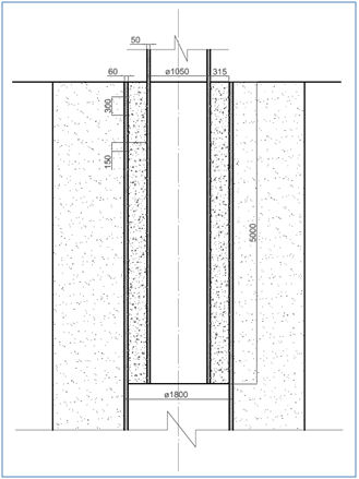
Length of the grout joint (Lg) = 5,000 mm.
Diameter of the pile (Dp) = 1,050 mm
Diameter of the sleeve (Ds) = 1,800 mm
Diameter of the grout (Dg) = 1,680 mm
Thickness of the pile (tp) = 50 mm
Thickness of the sleeve (ts) = 60 mm
Thickness of the grout (tg) = 315 mm
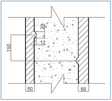
Shear key height (h) = 12 mm
Shear key spacing (s) = 300 mm
| Property | Structural Steel | Grout Material |
|
|
|
|
|
|
|
|
|
|
|
|
|
|
|
|
|
|
|
|
To model the geometry and analyse the structural behaviour of the joint, ANSYS Workbench 14.0 Academic Version has been used. The aim of this model is to approximately assess the stress values in the connection surfaces between the sleeve, the grout material and the pile. In order to avoid problems with the mesh of the model and because of the number of nodes limitation in the Academic Version of the software, the shear keys have not been included in the geometry.
This approach is justified by the fact that due to constraints of time and resources regarding software and computerization capacity, the inclusion of shear keys complicates obtaining results which aims to give an idea of what is the behaviour inside the joint rather than giving very accurate results. However, the inclusion of shear keys as further work is essential for obtaining accurate results, being able to predict failures of the joint under real loading conditions and practical design of the joint.
The geometry of the joint has been modelled with the dimensions that were described in 3.1. Dimensions. It has to be considered that the sleeves are driven deep into the seabed up to ground depths where they stand on a rock layer. The sleeves are normally surrounded by sand or mud, and the pile of the jacket is inside the sleeve connected to the sleeve by the grout. Inside of the sleeve, below the pile, there is no mud or sand since when the sleeve is driven into the seabed the mud is taken out. In the geometry of the model is included just the length of the sleeve corresponding to the grouted length where the pile ends and just the length of the pile contained in the grout connection.
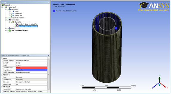
The geometry has been defined as three separated bodies: Jacket Pile, Sleeve Pile and Grout.
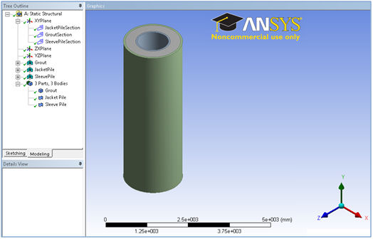
The geometry has been defined as three separated bodies which need to be connected in order to analyse the structural behaviour of the joint. Two connections have been defined: Grout to Jacket Pile and Grout to Sleeve Pile. ANSYS Workbench allows the user to choose among different types of connections. Bonded connections have been selected because this is the case that should be met in a real situation. By doing this, it is imposed in the model the condition of the bodies staying bonded and in this way the calculations will show the stress values that the bodies have to face in order to stay bonded and for the joint not to fail.
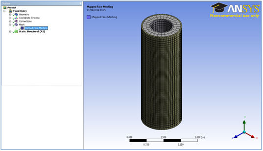
In order to mesh the geometry, some parameters have been set using the function Mapped Face Meshing. The selection of the parameters should be done carefully for meeting a compromise between acceptable refinement of the mesh and respecting the node limitation of the software. The mesh features selected are the following ones:
Method: Quadrilaterals Size function: On-proximity
Cells Across gap: 2 Proximity Min size: 0.10 m
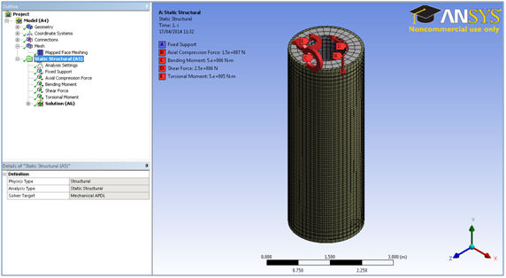
The loads applied to the grout joint were agreed with our industrial partner to get a realistic result after the structural analysis. The loading values are the typical loads transmitted to the pile at the head of the grouted connection coming from a 6 MW wind turbine supported by a four-legged jacket in a 40 m-water-depth location.
Axial Compression Force (FY) = 15,000 kN
Shear Force (FX) = 2,500 kN
Bending Moment (MZ) = 5,000 kNm
Torsional Moment (MY) = 500 kNm
It is important to explain that these loads are peak values and the real load conditions coming from wave loads, wind loads and loads coming from operation of the wind turbine will change all the time; this means that the loads are dynamic rather than static and a more profound analysis of the grout joint should consider this in order to study the fatigue behaviour of the joint.
The approach adopted in this simplified model is to consider the superposition of peak values for the different loads transmitted to the pile at the head of the grouted connection. In this way it is possible to study the maximum stress values that can be found on the connection surfaces.
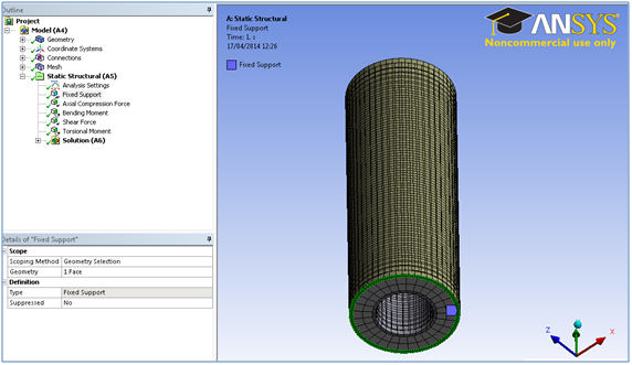
To model the surroundings constraints of the grout joint, a Fixed Support has been included on the sleeve at the bottom of the grout joint. The reason for modelling the support like this is that the sleeve is longer in reality and reaches a rock layer where it stands. Therefore, the bottom of the grouted connection corresponding to the sleeve is considered to be fixed to the rest of the sleeve.
In addition, in reality the sleeve is surrounded by mud and sand and they have a positive effect supporting the sleeve. However, mud and sand are normally soft and weak so they positive effect is considered to be small and it is disregarded in this model, choosing a conservative approach.
It is important to explain that these loads are peak values and the real load conditions coming from wave loads, wind loads and loads coming from operation of the wind turbine will change along the time; this means that the loads are dynamic rather than static and a more profound analysis of the grout joint should consider this in order to study the fatigue behaviour of the joint.
The approach adopted in this simplified model is to consider the superposition of peak values for the different loads transmitted to the pile at the head of the grouted connection. In this way it is possible to study the maximum stress values that can be found on the connection surfaces.
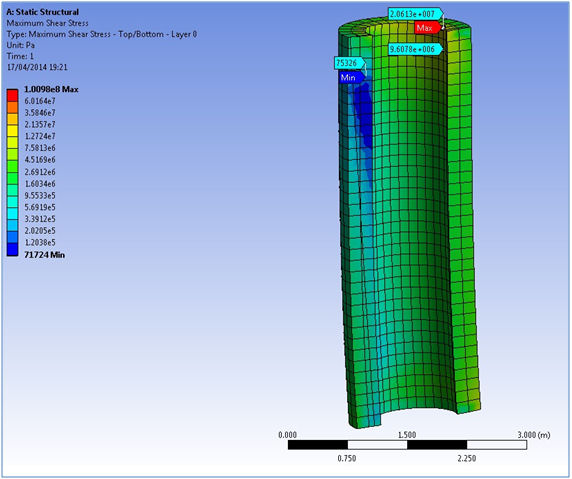
Once everything mentioned previously has been defined, the structural analysis was carried out. Static Structural tool in ANSYS Workbench was used. Concrete is a material that does not behave in the same way when it is working under tensile strain as it does under compressive strain. Concrete does not cope with tensile strain well and its tensile ultimate strength is very low compared to its compressive ultimate strength.
In order to study the grout material failure under compression and tensile strengths, the principal stresses are used to study the behaviour of the grout material. For each of the principal stresses, there is a maximum stress value and a minimum stress value. Positive stress values given by the software indicates that it is a tensile stress; negative stress values indicate a compressive stress. In addition, shear failure in the grout material and in the connection surfaces is to be studied. For doing so, the shear stress results have been obtained too.
An example of results is shown in the next picture.
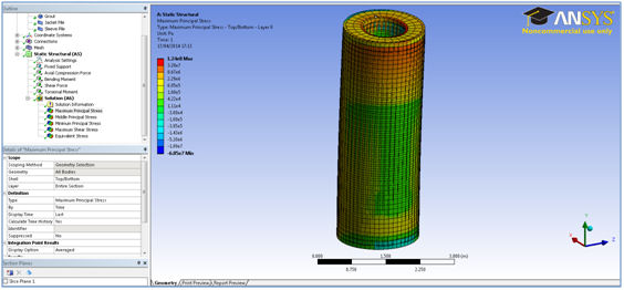
The results for the grout material will be presented next. It is worth noting that the loads have been applied on top of the pile. This produces resulting distortion on the head of the joint and the results are disproportionate in this part of the grout material. Therefore to get a realistic result it is necessary not to consider the results on the top edge of the grout material.
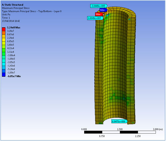
The maximum value corresponding to tensile stress is 16.85 MPa in the top edge of the grout material. As it has been explained before, this result is distorted and the true maximum tensile stress value is found on the bottom of the grout material as indicated in the picture. Hence the maximum compressive and tensile values for maximum principal stress in the joint are presented next:
Compressive stress = 0.35 MPa
Tensile stress = 6.05 MPa
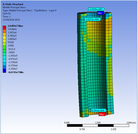
The maximum compressive stress value given by the analysis is 12.03 MPa on the top edge of the material so it is distorted. Moving away from the top edge we can observe a maximum value in the next level of nodes of the model (3.03 MPa). Therefore the maximum compressive and tensile values for middle principal stress are the following ones:
Compressive stress = 4.39 MPa
Tensile stress = 3.03 MPa
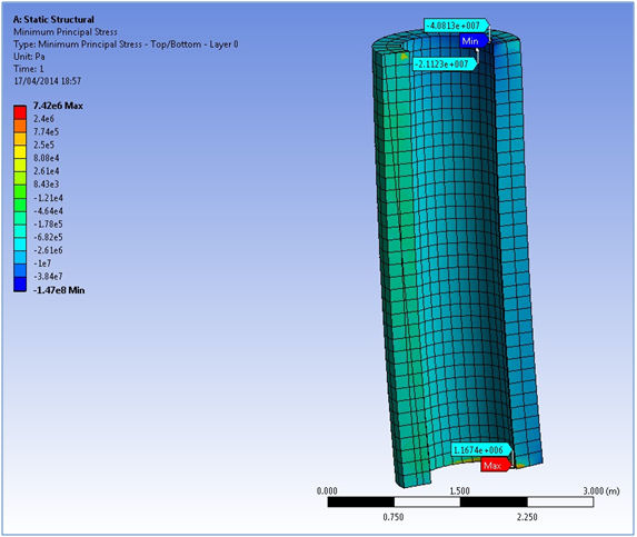
The maximum compressive value is given on the top edge (40.81 MPa). Proceeding in the same way as before, the results are checked below as shown in the picture. This area presents the maximum values of compressive stress. The maximum tensile values are obtained at the bottom of the grout material. The maximum values for minimum principal stress are shown next:
Compressive stress = 21.12 MPa
Tensile stress = 1.18 MPa