FEA
Finite Element Analysis - General Information
The finite element method (FEM) (or a more practical name finite element analysis - FEA) is a numerical technique in mathematics, which allows engineers to solve highly complicated structural problems. It is based on finding approximate solutions to partial differential equations, thus allowing engineers to simplify the mathematical model greatly. It is used in many different industries, varying from aerospace, civil to automotive. Many engineering disciplines - electromagnetism, fluid mechanics and thermodynamics - can be mathematically modelled with the help of FEM.Finite Element Analysis in our Project
In our project, the dimensions and angle of attack were found with the help of CFD analysis done by Thomas Nevalainen (our project collaborator). From here on, stabilization of the hydrofoil was an issue. A system of four cables designed for this purpose.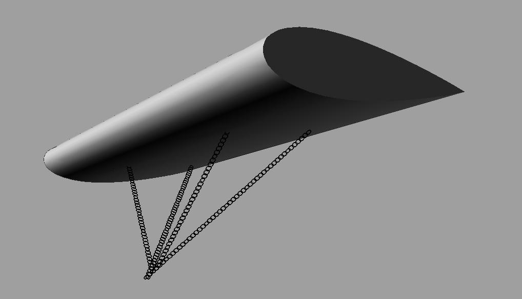
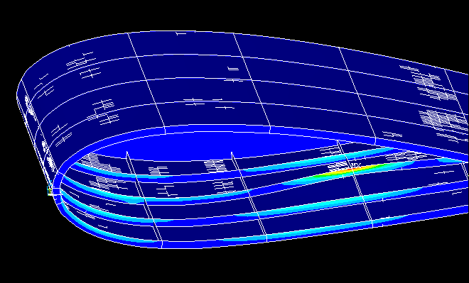
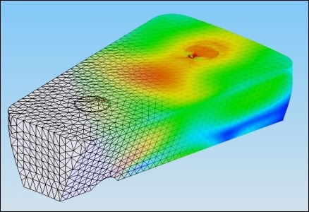
These cables are attached to four fixing point located on the lower surface of the hydrofoil. These cables are trying to hold a massive 7x17 m2 body made of steel under heavy forces. Fixing points are under tremendous stress due to the force created by lift and buoyancy. An FEA analysis was required to assess the safety of the system and determine the minimum thickness of the hydrofoil. The software that was used in this process is ANSYS, an FEA computer program.
Assumptions and data for FEA
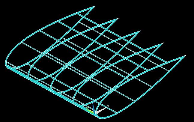
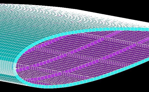
-Chord length= 7 m
-Width= 17 m
-Lift= 385 kN
-Drag= 10 kN
-Buoyancy= 100 kN
-Hydrodynamic pressure= input from CFD analysis
-Young's modulus= 200 GPa
-Poisson Ratio= 0.3
Results of FEA
-General thickness= 7 mm
-At fixing points (both frames and structure reinforced)= 15 mm
-Maximum displacement= 13.7 mm
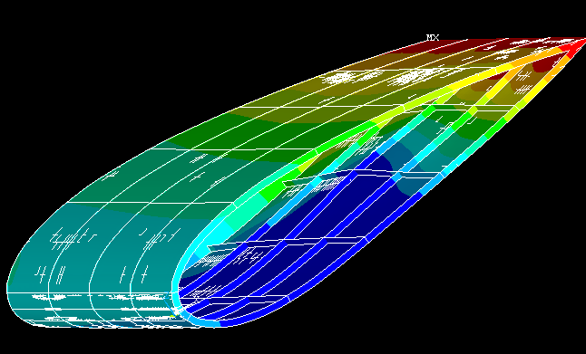
-Yield strength of steel= 250 MPa
-Maximum stress= 200 MPa