


Heat Pump Design
1. Heat Pump Water Heaters
CO2 transcritical cycle is used for the production of hot water in water heaters due to its high efficiency. It can supply high temperature hot water varying from 60 to 95 degrees so it therefore requires no supplementary heating. At optimum gas cooler pressures, the cycle of the heat pump water heater in a T-H diagram is shown in figure 1 where city water is at 5 degrees and domestic hot water (DWH) is at 70 degrees.
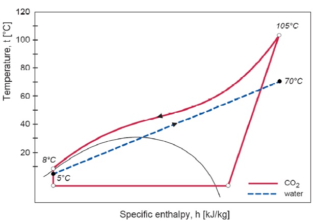
Figure 1: Temperature Enthalpy Diagram for Heat pump water heaters
The water heater in the heat pump consists of two heat exchangers, low pressure inlet valve, and a tank which receives water. A more simple sketch of the heat pump water heater is shown in figure 2. The water is taken from the top of the tank at point A at 60 to 95 degrees and mixed with cold water at 50 to 55 degrees. This mixed water is then used to supply the demand on the system. The city water enters the tank from the bottom at point C to cover the water drawn. A pump operates between D and E to circulate water. Water mass flow rate is adjusted and pressure is optimised to achieve as maximum a COP as possible.
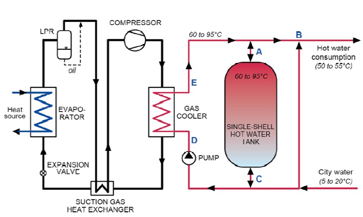
Figure 2: Principle sketch of heat pump water heater with single DHW tank.
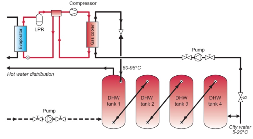
Figure 3: Non residential heat pump water heaters with many single DHW tanks
For non residential purpose, many hot water tanks can be connected in series as shown in figure 3.
2. Comparison of different heat pump water heaters:
Four different heat pump water heaters are analysed to compare their performance ( Hjerkinn, 2007)
- A. R134 heat pump with condenser and desuperheater (DSH)
- B. R134a heat pump with subcooler (SC), condenser and desuperheater
- C. R134a heat pump with suction gas heat exchanger (SGHX), condenser and desuperheater
- D. CO2 heat pump with single counter-flow gas cooler, optimised gas cooler pressure
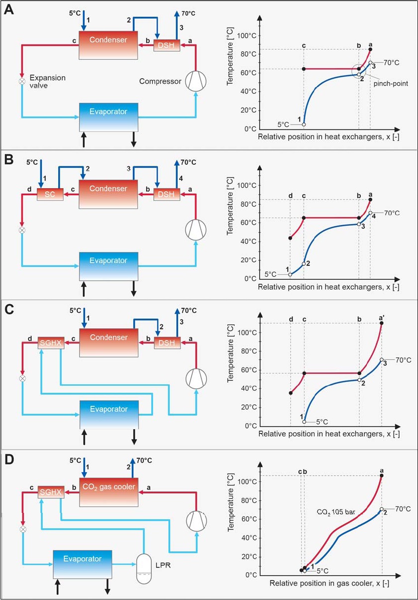
Figure 4: System designs for different heat pump water heater and temperature profile for heat rejection process
Results obtained by Hjerkinn are given in figure 5 and 6 which show that CO2 heat pump water heaters give a better COP through the range of inlet water temperature and evaporator temperature when compared with even most effective R134a heat pump water heaters.
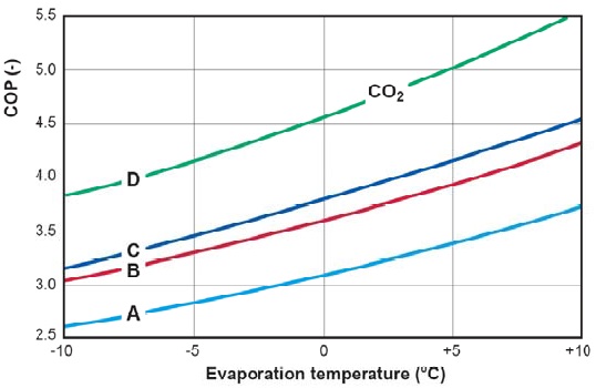
Figure 5: COP vs evaporator temperature for different heat pumps.
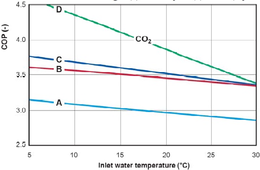
Figure 6: COP as a function of inlet water temperature for different heat pumps.
3. Laboratory Testing of CO2 Water heaters:
In the last few years, different prototypes of heat pumps have been tested by different people. They all used a low pressure receiver, a suction gas heat exchanger and a counter flow tube in tube heat exchanger.
a. Laboratory Testing of a 50 kW prototype CO2 HPWH – Norway
It was tested in 1998 in Norway at SINTEF energy research Norway. The prototype is shown in figure 7. COP values for a capacity range of 5 to 20 kW were calculated and analyzed by Rieberer and Halozan (1997), Hwang and Radermacher (1998) and Saikawa and Hashimoto (2000) and many others.
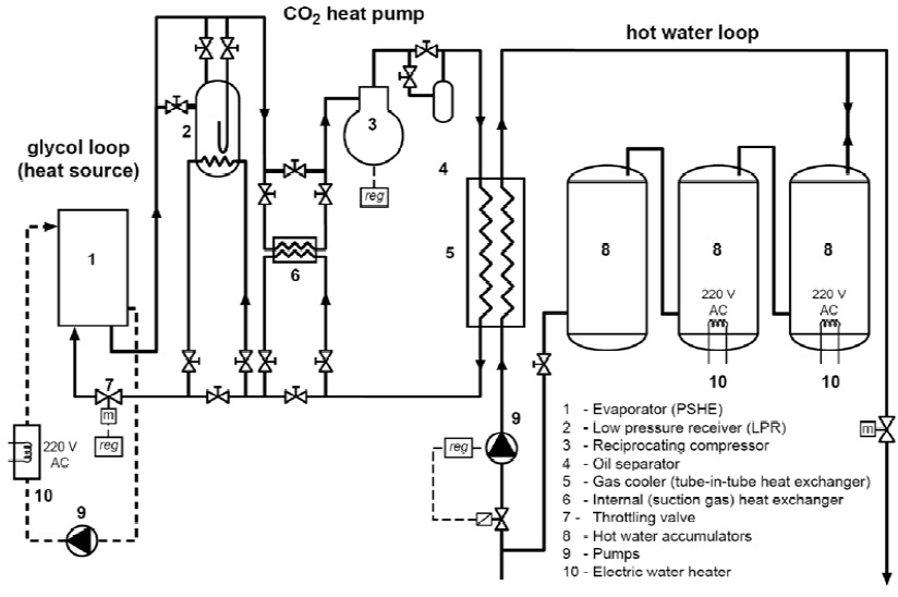
Figure 7: Prototype tested at SINTEF energy research (Neksa et al., 1998)
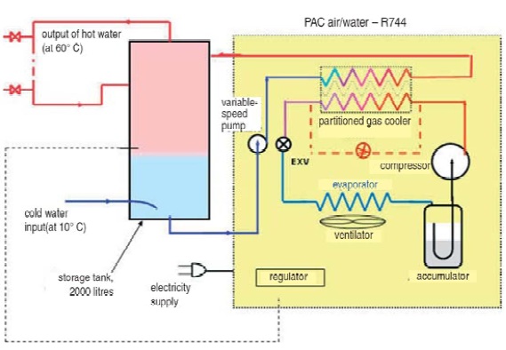
Figure 8: Sketch of prototype made in Switzerland (Anstett, 2006)
b. Field Testing of a 60 kW Prototype CO2 HPWH – Switzerland
This system was tested in Switzerland and a sketch is shown in figure 8. The system was analyzed at 70 degrees hot water and 20 degrees city water and with varying ambient temperature.
c. Field Testing of a 60 kW Prototype CO2 HPWH – USA.
This prototype was tested in USA and was tested for a range of hot water from 60 to 80 degrees at a flow rate of 90 litres/h. These units were not commercialised. Sketch of this prototype is shown in figure 9
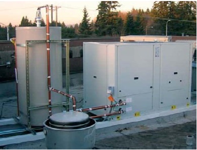
Figure 9: Sketch of prototype used in USA (Sienel, 2006)
4. Eco Cute Commercially available:
Japanese Government introduced eco cute heat pumps as they are energy efficient and environment friendly. There are many Eco cute residential manufacturers as well as commercial manufacturers. Examples of manufacturers of Commercial and residential eco cute heat pump water heaters are shown in figure 10.
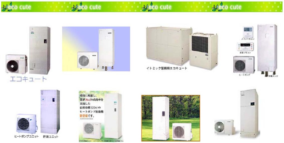
Figure 10: Japanese eco cute heat pumps from Denso, Corona, Daiken, Hitachi, Matsushita, Mitsubishi and Sanyo
5. Integrated Systems: Space heating and Hot water heating:
Integrated heat pumps for houses can do both space heating and water heating. There are three modes in which integrated CO2 heat pumps can work.
- Hot water heating only
- Space heating only
- Simultaneous hot water and space heating
5.1: Possible Designs of Gas Cooler and DHW tank
The integrated CO2 heat pumps can have following designs
5.1.1: External CO2 gas cooler
In these systems, CO2 external gas cooler is attached to a single DHW tank. Gas coolers can be connected in a further three ways.
A. A single gas cooler unit,
In this design, there is a single gas cooler which is connected to a single DHW tank and heat exchanger. Space heating can be of three types as given in following figure with names of T1.1, T1.2 or T1.3.
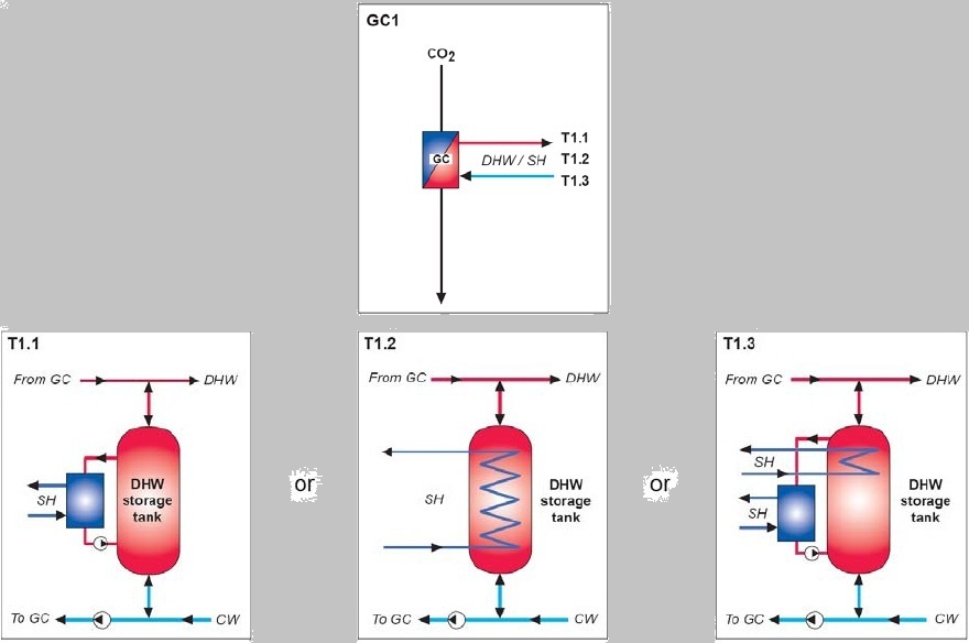
Figure 11: Configuration of single external gas cooler and possible designs for space heating heat exchangers and DHW tank
B. A bipartite gas cooler (two gas cooler units, serial or parallel connection on the CO2 side)
In this type of design, there are two gas coolers in the system. Consider the figure 12 below. In figure 12, GC2.1, GC2.2 and GC 2.3 are the figures which show configurations of 2 gas coolers in parallel and series. When they are attached separately with T2.1 they can provide three different designs. In case of GC2.1, there are two parallel gas coolers. It can provide high temperature space heating and water heating. COP in the case of only space heating and only DHW is same but combined mode will give lower COP. So in average it is giving lower COP than baseline system.
In the case of GC2.2 and 2.3, there are two gas coolers in series and space heating gas cooler is located before and after the DHW gas cooler respectively. COP in the case of only space heating and only DHW is the same but combined mode will give lower COP. So in average it is giving lower COP than baseline system.
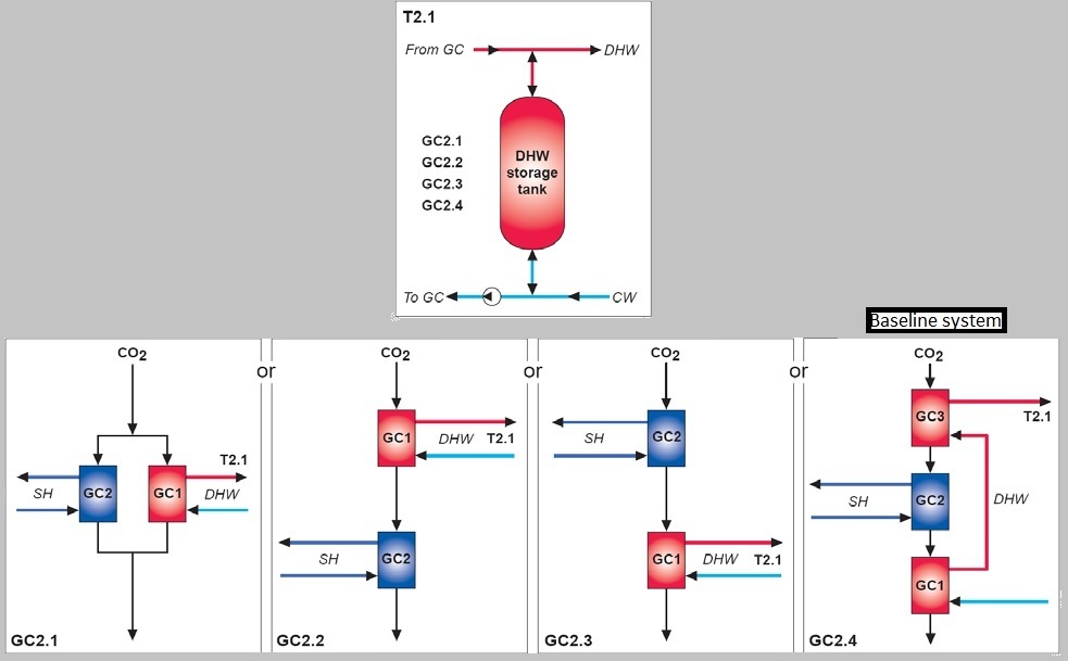
Figure 12: Configuration of bipartite and tripartite gas coolers connected to single DHW. GC=gas cooler, CW=city water
C. A tripartite gas cooler (three gas cooler units, serial connection on the CO2 side)
Figure 12 shows the configuration with name of GC 2.4. It shows that there are three gas coolers which is known as tripartite gas cooler design. The gas cooler is first used for preheating of DHW, then for space heating and in last for reheating of DHW. It is the most efficient system design.
5.1.2: Integrated CO2 gas cooler and DHW storage tank
In these systems the gas cooler is designed as a tube coil and then put inside the tank in some way. Consider the figure 13 given below.
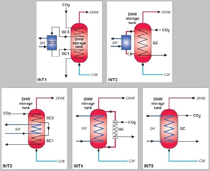
Figure 13: Different designs of Integrated gas cooler and single DHW storage tank
5.2: Integrated CO2 Heat Pump System Using a Tripartite Gas Cooler
The most energy efficient design is that in which a tripartite gas cooler is used which means there are three gas coolers in series and the first is for preheating of DHW , second is for space heating and third is for reheating of water (Stene 2004, 2005). This design can be used for space heating only, DHW only and for combined mode as well. The design is shown on the figure below.
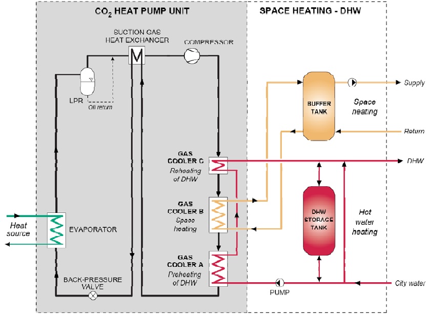
Figure 14: Design of Baseline CO2 heat pump with tripartite gas cooler (Stene, 2004)
Some characteristics of the above described designs are given in the figure below.
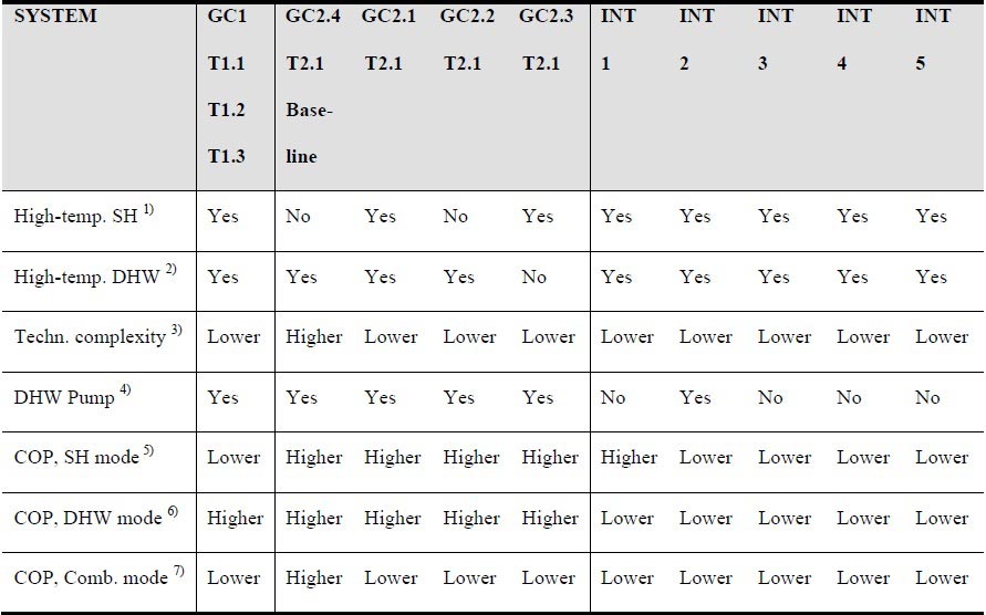
Figure 15: Important characteristics of different configurations described above
1.Capability of providing high-temperature space heating in Combined mode (tSH>50ºC)
2.Capability of providing high-temperature DHW in Combined mode (tDHW>60ºC)
3.Technical complexity of the gas cooler units, heat exchangers and DHW storage tank system compared to the baseline CO2 heat pump system: Higher = as baseline system, Lower = simpler than baseline system
4.Requirement of a pump in the DHW circuit – required electric input power to the pump
5.COP in the space heating (SH) mode: Higher = same COP as baseline system, Lower = lower COP than baseline system
6.COP in the domestic hot water (DHW) heating mode: Higher = same COP, Lower = lower COP than the baseline system
7.COP in the Combined heating mode: Higher = same COP, Lower = lower COP than the baseline system
5.3 Commercially Available Integrated CO2 Heat Pumps
Integrated CO2 systems were first developed by Japanese market in 2001. Denso Corp. Ltd sold 100,000 units by 2007. In European market these systems were introduced by Sanyo manufacturers. Sanyo integrated CO2 heat pump sketch is shown in figure below.
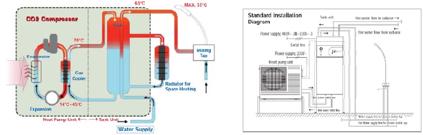
Figure 16: Sanyo integrated CO2 heat pump using ambient air as heat source
There are many other Japanese manufacturers who are making these CO2 integrated systems and more information can be found out at http://www.R744.com.
Bibliography
1. Hjerkinn, T., 2007: Analysis of Heat Pump Water Heater Systems for Low-Energy Block of Flats. Master thesis at The Norwegian University of Science and Technology (NTNU), November 2007. EPT-M-2007-24.
2. Rieberer R., Stene J., Nekså P., Jakobsen, A., 2005: CO2 Heat Pumps – Background and Outlook. Chapter 9 in ”Statusbericht des Deutchen Kälte- und Klimatechnischen Vereins – Kohlendioxid, Besonderheiten under Einsatzchancen als Kältemittel”, November 2005.
3. Stene J., 2004: Residential CO2 Heat Pump System for Combined Space Heating and Hot Water Heating, Doctoral thesis at the Norwegian University of Technology and Science (NTNU), ISBN 82-471-6316-0 (printed ver.), ISBN 82-471-6315-2 (electronic ver.).
4. Stene J., 2005: Residential CO2 Heat Pumps for Combined Space Heating and Hot Water Heating – System Design, Test Procedures and Calculation of SPF. SINTEF Report TR A 6102. ISBN 82-594-2806-7. SINTEF Energy Research, Norway.
5. REULENS, W., ‘Natural Refrigerant CO2 EDITED BY WALTER REULENS OCTOBER 2009 (Leonardo project)’ http://www.atmosphere2009.com/files/NaReCO2-handbook-2009.pdf
6. EVERYTHING R744 http://www.r744.com/