INTRODUCTION
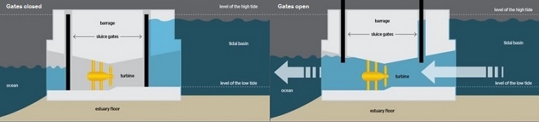
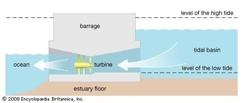
A tidal barrage is a dam-like structure with turbines placed at the bottom of the reservoir. The dam creates a barrier between the sea and the tidal basin taking advantage of the change in the tide levels to produce power. Gates are used, opening and closing regularly to control the flow of water and maximize the power generation. In some cases, pumping may be performed, using electricity from the grid, to further raise the water levels in the basin, creating a larger difference between the sea and the basin water levels (head of water) and thus resulting in the increase of power generation.
Source: Encyclopaedia Brittanica
There are various tidal barrage schemes proposed across the world but few of them have come to fruition. Most of the operating tidal barrages have been built on the estuaries of rivers, and because of that, multiple environmental implications had to be considered and overcome, a generally time-consuming and costly process. The construction of a barrage is in itself a very costly endeavour. A large (multi-MW or GW) tidal barrage’s cost is usually in the billion range.
Some examples of Tidal Barrage projects can be seen in the table below:

A tidal barrage worth highlighting is in La Rance, France, so far the only existing tidal barrage in Europe and it has been operating since 1966.
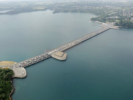
Source: EDF
SIMPLIFIED TIDAL BARRAGE
The proposed tidal barrage on the Isle of Whithorn Bay is a small hydro scheme and its maximum installed capacity is estimated to be under 1MW. With that in mind, we considered how it would be possible to reduce the overall cost of the application as much as possible. The idea we came up with was a slightly altered version of the conventional.
Instead of controlling the flow of the water passing through the turbines, we decided on reducing the overall control needed over the operation of the tidal barrage and instead examined a tidal barrage with no gates, a Simplified Tidal Barrage.
This idea keeps the structure of the barrage but instead of controlling the passage of water with movable gates, it operates without the use of gates, allowing continuous flow of water through the turbine tunnel. This eliminates the need for accurately timed switching of the gates and the expense of the associated control systems. There is still though the need for some control, in order to regulate the electrical load on the generator and its speed of rotation.
In the context of reduced control, we additionally considered that pumping is inappropriate for this application, since it would require some external source of power (the grid) and accurately timed mode switching. Furthermore, since our main objective is to eliminate the risk of flooding in the harbour, it would not serve our purpose to increase the water levels in the basin area.
Since allowing the water to flow freely inside and out of the basin, the hydraulic head over the turbines is going to be reduced compared to a conventional tidal barrage. To compensate and maximize the energy capture per cycle, we considered bidirectional generation, which means using appropriate turbines that operate both during flood and ebb tides. Because we would have low hydraulic head, for this application we would need low-head turbines, such as Kaplan bulb. Due to the factors mentioned above, a Simplified Tidal Barrage would have a less effective energy capture than a fully regulated tidal barrage with timed gate movements, but it is still an idea worth implementing for small tidal barrage schemes with low head of water.
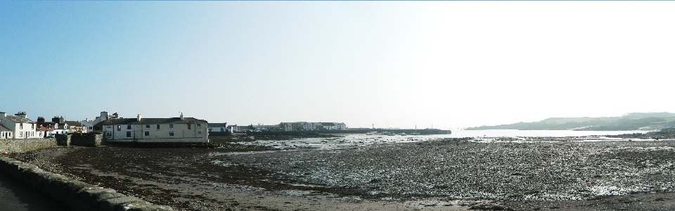
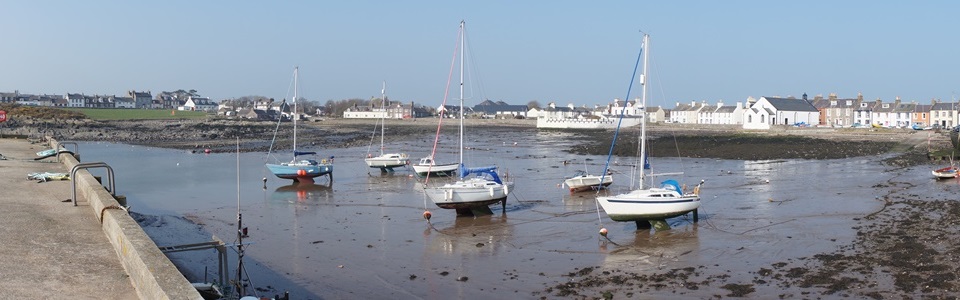
BARRAGE LOCATION
The location of the tidal barrage was decided by taking into consideration different parameters of the site, like the basin area that would optimize power production in relation to the depth profile of the seabed.
Because the tidal barrage is basically a barrier between the sea and the harbour, there was need to include a ship gate in the design for the boats to have access to the harbour.
As it can be seen from the sketch below, the turbine housing (including 4 turbines) occupying a considerable area, needed to be placed in a deep enough position with a constant seabed.
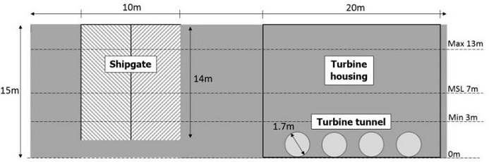
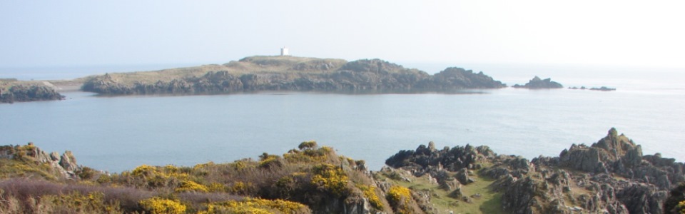
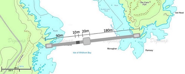
The figure below shows the position of the proposed barrage on the map, with the dimensions and the relative position for the shipgate (10m) and the turbine housing (20m). Electrical infrastructure for the grid connection can be positioned at both ends of the barrage. Power take-off towards the site of the isle head could be difficult due to the sensivity of the ruins of St. Ninian's Chapel and walking routes.
TURBINE POSITION
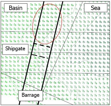
The position and size of the turbine tunnel should be designed with great attention. The water depth should be sufficiently low to prevent dry-out and cavitation. If the depth is not large enough, air bubbles can form on the turbine blades which can cause serious damage to the turbine blade surface due to cavitation. Cavitation is when vapour-filled bubbles occur caused by a local pressure drop. They eventually collapse in regions of higher pressure. Therefore, it is sometimes not possible to use larger turbines without dredging to ensure power production below cavitation depth (Sustainable Development Commission). With regards to this fact, a position of the turbine tunnel is chosen which lies in approximately 7m depth in relation to the mean sea level (MSL) – see red circle in below figure. The minimum water level at this point is roughly at 3m.
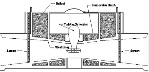
The sketch below demonstrates the structure of the tidal barrage at the point of the turbine housing, specifically the cross sectional area of the turbine tunnel with a clear view of the inlet and outlet of the tunnel and the constituent parts of the structure. The screens at the entrance and exit of water should not be confused with sluice gates, they are a means of containing rubbish from inserting the tunnel and obstract the operation of the turbine, as well as prevent the accumulation of sediment on the turbine runner. You can see further the location of the turbine generator in the compartment above the turbine, and the placement of other components, such as the removable hatch (for maintenance reasons) and the concrete construction below and above the turbine tunnel.
WATER LEVELS
The turbine tunnel diameter defines the power output of the barrage and the water level inside the basin.
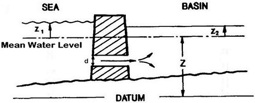
Source: Simplified Tidal Barrage for Small-Scale Applications by Andrew Grant
- z: from datum to mean water level
- z1: from mean water level to water level outside the basin
- z2: from mean water level to water level inside the basin
- d: Turbine tunnel diameter
Using a too large a diameter the water level in the basin will change the same way as the sea water level outside the basin. This behaviour is not desirable, since the water head above the turbine determining the power generation is insufficient. On the other hand, if the turbine hole is designed too small, the water level inside the basin will not be changing which would then result in water quality problems in the harbour. With this knowledge it is possible to control the water level inside the basin and therefore to prevent flooding in the harbour. The overall aim of the design is for an optimum tunnel diameter, which will be a compromise between maximum power output and minimum flood risk for the harbour during a severe storm scenario.
Different turbine tunnel diameters have been assessed to find the best option. As the diagram below shows.
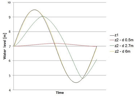
A small diameter, for instance of 0.5m (red line), has the result of the water level inside the basin showing only a slight change. On the other hand, a diameter of 6m (yellow line) causes the water level in the basin to follow the behaviour of the water outside the basin, as can be seen from the above diagram, the yellow line and the black line nearly overlapping.
The optimum diameter for a Cd value of 0.9 has been assessed to be between 2.6m to 2.8m with an average peak power output of approximately 420kW using the mean tidal range of 5m.