Introduction
The construction procedure of XL monopiles, used as support structures for offshore wind turbines, comprises of the following phases:
Each of the above mentioned phases have been thoroughly examined in order to identify the limits of the existing machinery and find out under what conditions it is suitable for XL monopiles. Although XL monopiles follow similar manufacturing, transport and installation techniques, as ordinary monopiles, their size poses a significant challenge.
Manufacturing
Tubular steel piles are shaped from plates using 3 or 4 rolls bending machines, usually located in a nearby factory (Offshore-technology.com, 2015).
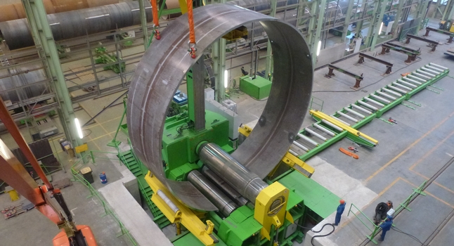
Figure 38. Plate bending (Rechargenews.com, 2015)
The main design parameters that affect the manufacturing stage are the diameter, wall thickness and the depth of the section of the pile (Hmc.heerema.com, 2015). The following average values have been taken into consideration:
Table 18. Plate Dimensions
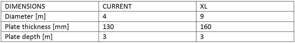
As it can be seen in the table, in the case of XL monopiles these dimensions reach higher values than the ones used for the ordinary monopiles. The question in hand is whether the available machinery for monopiles will be able to shape XL monopiles despite of this fact.
The limits of the existing machinery are: around 320 mm for the plate thickness and 4.3 m for the depth of the section of monopile (Hmc.heerema.com, 2015). Hence, it can be concluded that the existing machinery can be used for manufacturing XL Monopiles. However, as monopiles increase in size the need for significant increase in the size and weight of the machinery will become inherent. It means less available machines and therefore, more expensive ones. Consequently, it will lead to an increase of the manufacturing costs.
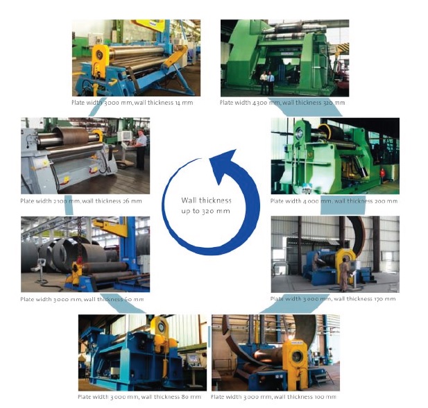
Figure 39. Manufacturing machines according to the plate wall thickness (Hmc.heerema.com, 2015).
Transport
Vessel types
Vessels used for the transport of monopiles are classified as:
Platform supply vessels
Platform supply vessels are mainly used for the transport of the monopiles from the manufacturing site to the operation harbour (not for the transport to the offshore construction site), (European Union, 2013).
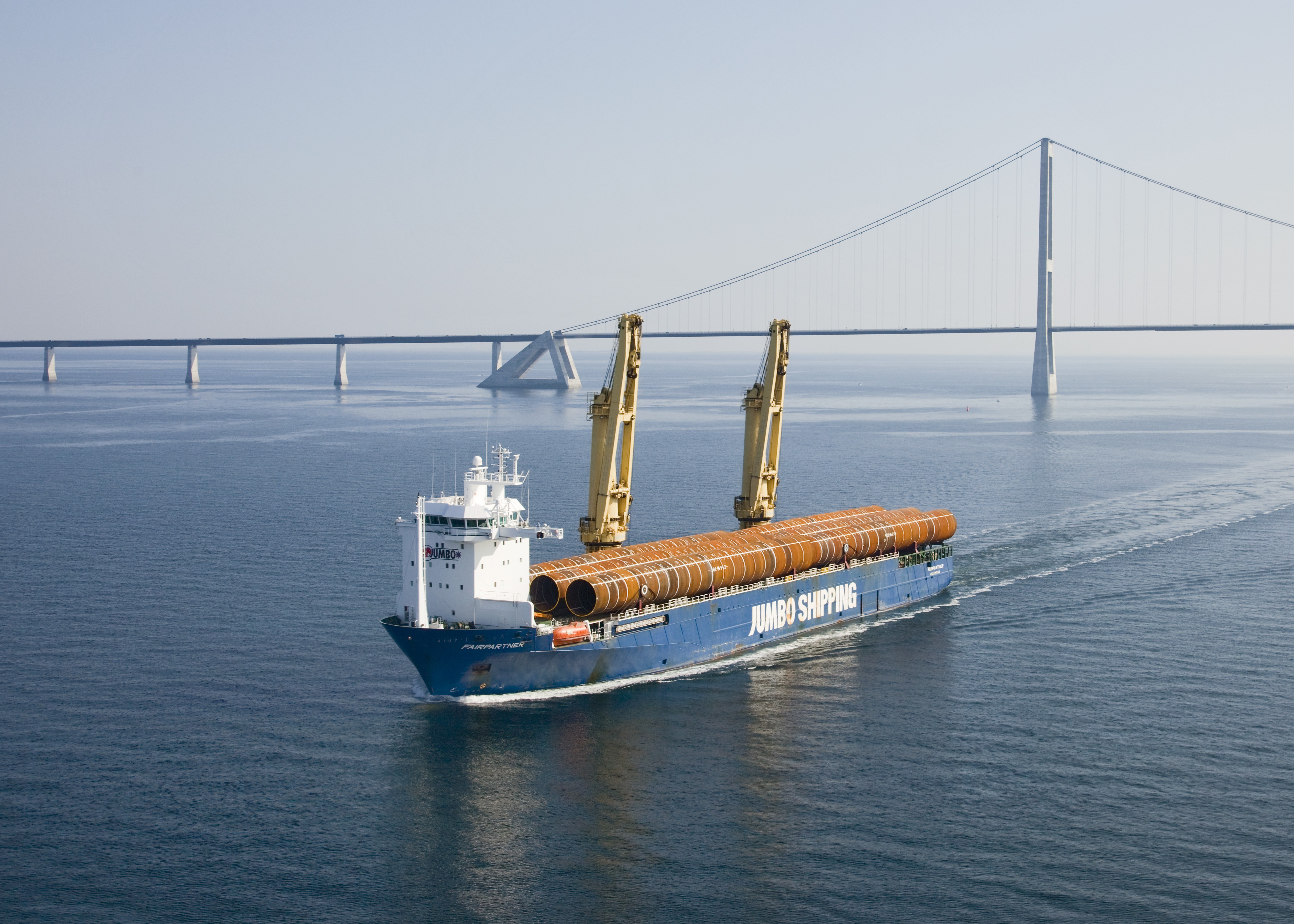
Figure 40. Platform supply vessel (Jumbo Shipping, 2015)
Barges and tugboats
Barges are flat bottomed boats, usually not self-propelled, used to transport monopiles to the installation site. They require a tugboat which tows the barge or the monopiles directly. The transport configuration using these vessels can be (Kaiser and Snyder, 2013):
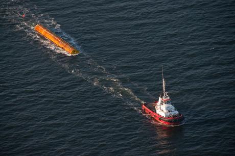
Figure 41. Tugboat and floating MP (Windpoweroffshore.com, 2015)
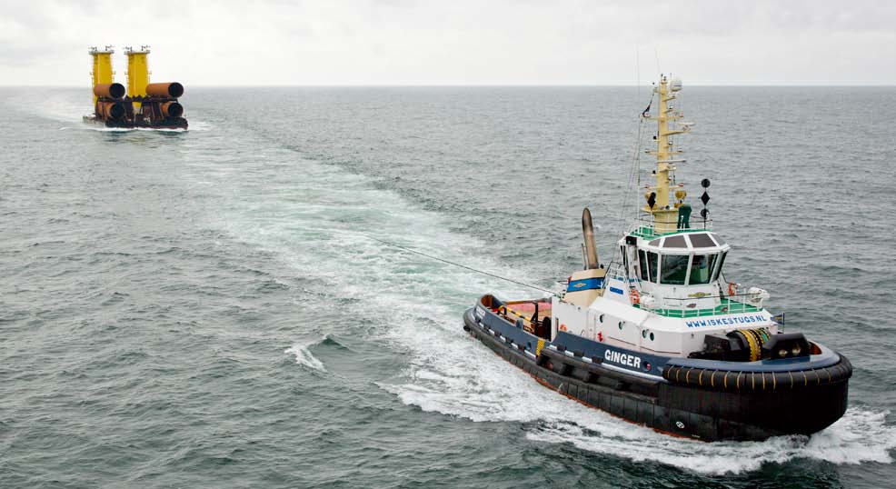
Figure 42. Tugboat and barge configuration (Heavyliftspecialist.com, 2015)
Conclusions:
The literature research has indicated that:
Installation
Installation Vessels
Vessels used for the installation of the monopiles are the same ones used in the oil and gas industry. In other words, a number of vessels already exists. On the other hand, it is apparent that the available vessels cannot be used for the two activities simultaneously, posing limitations on their availability (Kaiser and Snyder, 2012).
The available vessels are classified as:
Jack-up platforms
Jack-up platforms are comprised of a buoyant hull and a number of legs that penetrate in the seafloor in order to raise the boat above the water level and provide a stable base for the operation (European Union, 2013). They have been optimized for offshore oil and gas industry and are the most common type in offshore wind market for the installation of the monopiles (Windpoweroffshore.com, 2015b).
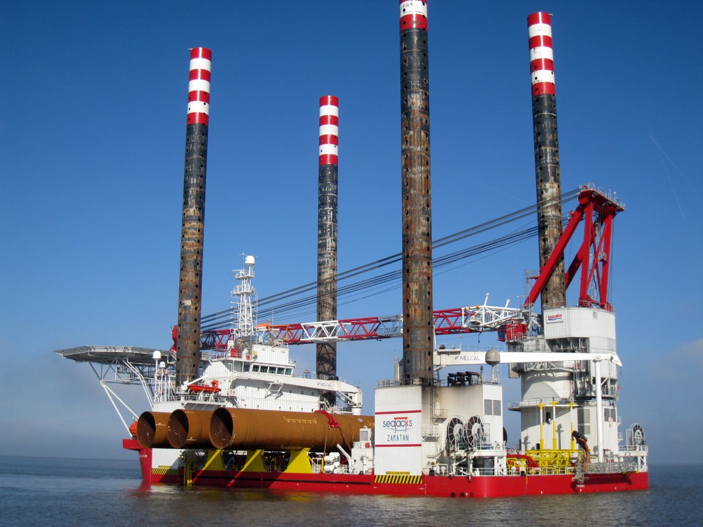
Figure 43. Jack-Up platform (Conbit, 2015)
Jack-up platforms have certain limitations detailed bellow (European Union, 2013):
Heavy-lift vessels
Heavy-lift vessels have the highest crane capacity and also provide favourable stability characteristics relevant to the installation of monopiles (European Union, 2013).
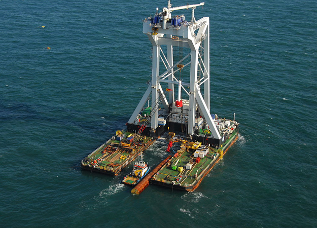
Figure 44. Heavy lift vessel (Renewable Energy News, 2014)
However, heavy lift vessels have the highest cost (availability related to oil and gas industry) (Windpoweroffshore.com, 2015b).
Installation challenges
The installation phase of monopiles has been analysed in order to identify the challenges of installation of XL monopiles. The usage of the most common type of vessel has been studied, corresponding to the jack-up platform (Kaiser and Snyder, 2012). The purpose is to find out whether these boats can be used for the new XL monopile technology and identify the limits of their application.
Monopile installation vessels: Jack-up platforms
A sample of 30 jack-up vessels has been taken in order to create a database with the maximum lifting capacity and maximum depth that they can work at. The data has been taken from Vessels.offshorewind.biz, (2015). With this information the following issues have been analysed:
Using the database a distribution of the crane capacity has been plotted. The average maximum working depth for the range considered has also been taken into account. The results are shown in the following graph which displays the current situation of the jack-up vessels regarding the parameters of the study.
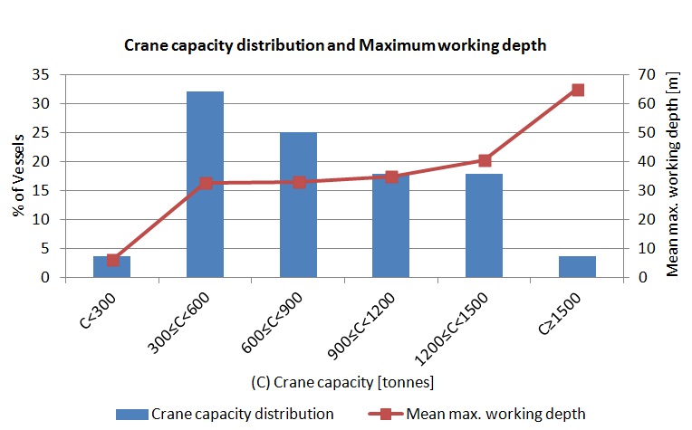
Figure 45. Jack-up vessel capacity
From the graph it is apparent that the current range of maximum Jack-up vessel lift weight varies between 100 and 1500 tonnes. The majority of the available vessels has a lift weight range of 300-600 tonnes. Moreover, the mean value for the crane capacity is 743 tonnes. The maximum working depth is in the range of 6 to 65m and increases with the crane capacity.
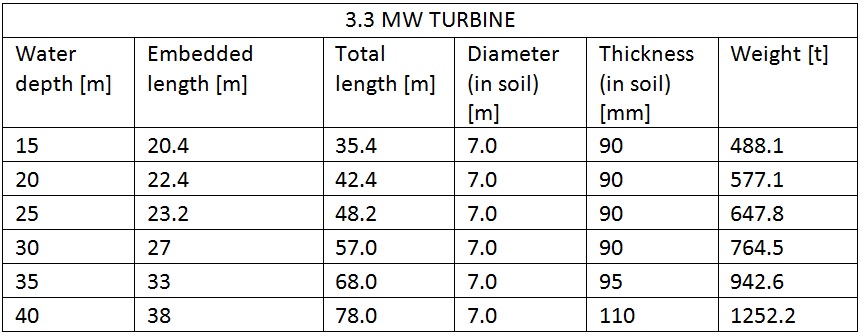
The dimensions and weights of monopiles as derived from the structural design are:
Table 19. 8.0MW turbine-MPs dimensions.
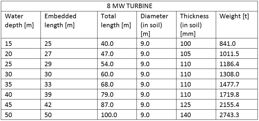
Table 20. 3.3MW turbine-MPs dimensions.
The information above has been presented in a graph adding the limit imposed by the crane capacity (maximum crane capacity available: 1500 tonnes) and the average value of lifting (mean crane capacity available: 743 tonnes).
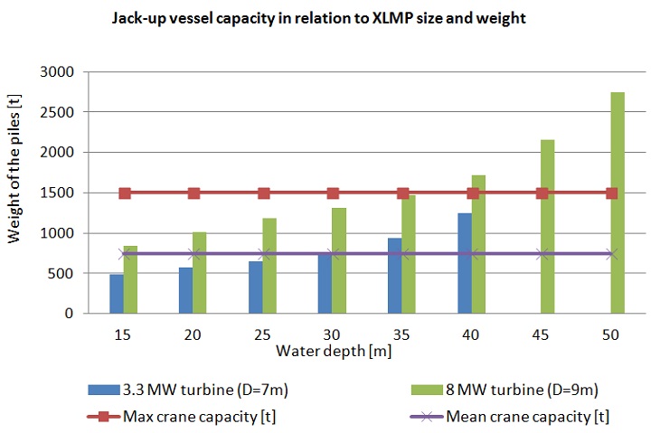
Figure 46. Jack-up vessel capacity in relation to monopiles weights
With the currently available Jack–up vessel crane capacity (considering the maximum crane capacity) it would be possible to install monopiles considered in our structural design up to depth of 35m for turbines of 8.0MW and 43m for the 3.3MW ones. Moreover, the half of the available vessels cannot install turbines of 8.0MW at any depth because of their crane capacity and can install turbines of 3.3.MW just until a depth of 30 meters.
Conclusions:
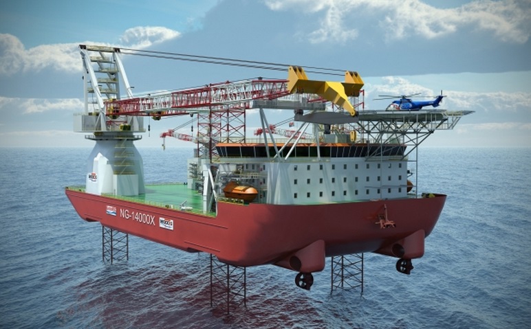
Figure 47. Seajacks Skyla Jack-up Platform (Seajacks.com, 2013).
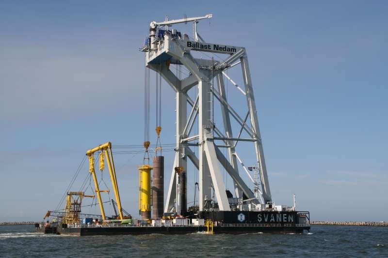
Figure 48. Ballast Nedam Svanen Heavy Lift Vessel (Shipspotting.com, 2015)
Installation Technology
In order to identify the appropriate technology regarding the installation of XL monopiles it has been considered important to identify the governing parameters of installation of monopiles, which are (Ben C. Gerwick, 2007):
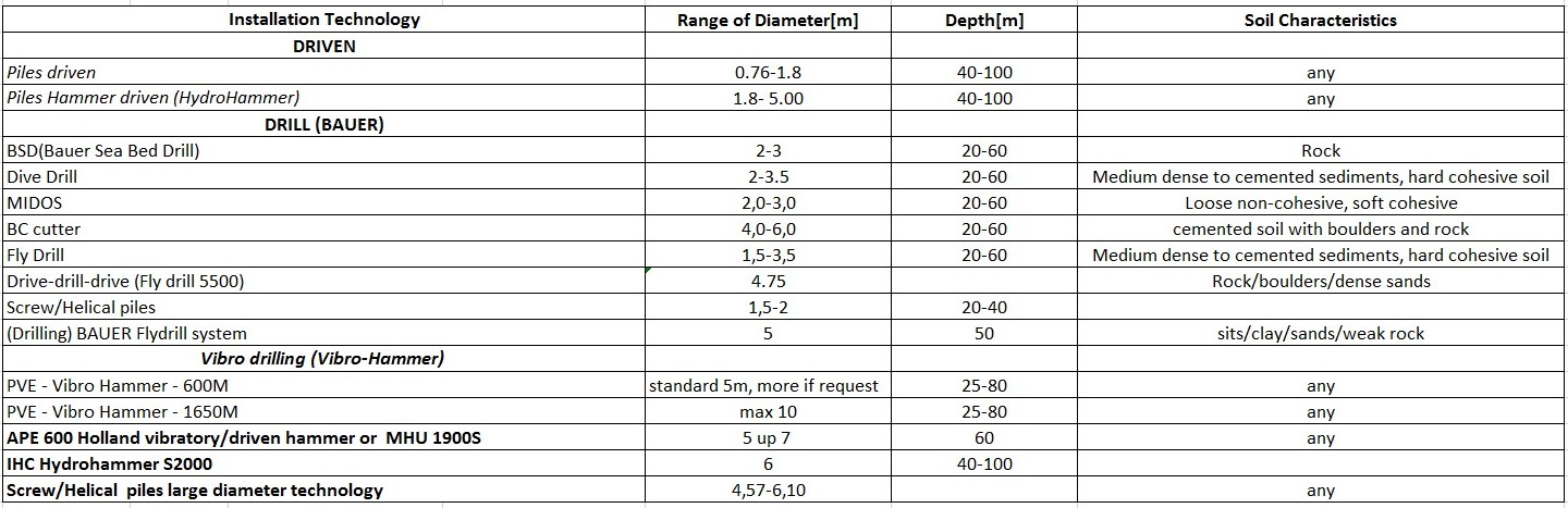
Table 21. Installation technologies (Ben C. Gerwick, 2007)
The different installation technologies are:
Deeper Waters
As the water depth increases, the length and diameter of the pile increase as well. The research has indicated that for diameters over 6m and water depths up to 80 meters the vibro-hummer technology is one of optimum technologies available.
The machines available for this type of technology are (Ben C. Gerwick, 2007):
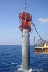
Figure 49. Vibro Hammer (Trade)
The second technology, applicable for the XL monopiles is the Vibratory driven-hammer. The machines available for this type of technology are (Wybren D., V., 2011):
The vibratory driven–hammer technology is available with a maximum diameter of 5m up to 7m and a drilling depth of 60m in any soil characteristics.
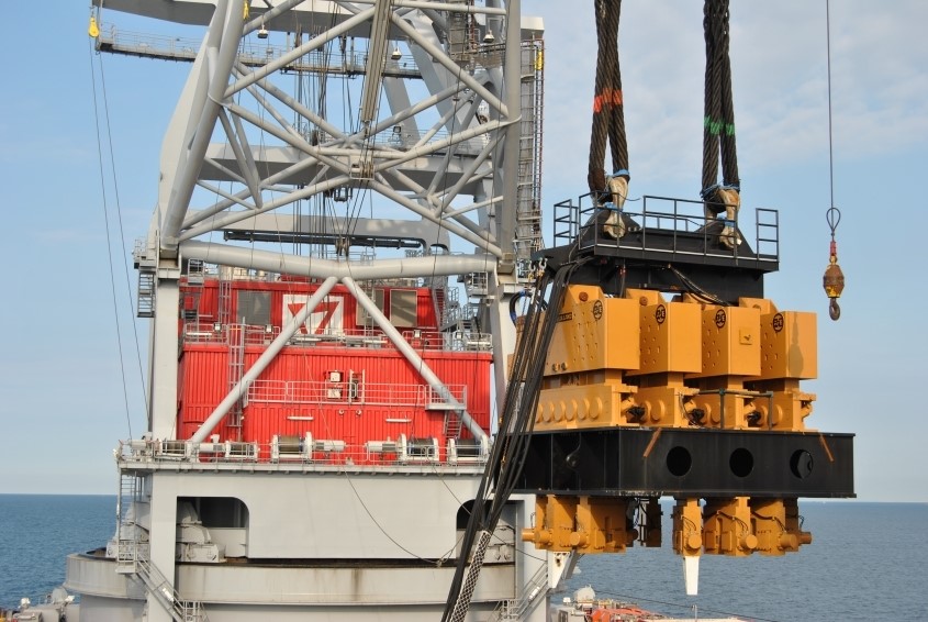
Figure 50. APE 600 Holland (HOLLAND)
The pile installation could also be performed using a drive-drill technique, but the cost is often prohibiting.
The vibro-hummer technology offers a competitive option cost wise. Furthermore, less noise is emitted during the pile installation, limiting the environmental impact associated with this stage of piling.
When choosing the minimum wall thickness of the pile, the following equation should be considered in order to prevent localized buckling, but also to help increase penetration under the hammer blows.
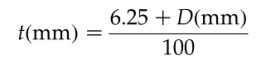
Figure 51. Pile Wall thickness (Ben C. Gerwick, 2007)
Installation techniques
The installation technique of an array of monopile substructures depends on the number of monopiles and the type of vessels available. When piles arrive at the site are upended by a crane or some other pile gripping machine. This is normally referred to the loading that determines the required crane capacity.
Once this part of the process is completed, the pile is then driven into the seabed where a hammer or a driller (in situations where shallow bed rock is present) are used.
The duration of installation depends on the type of soil as well as the size of the pile and the weight of the hammer used. In addition to the above, the drilling process, will also add to the installation time. After the monopile is put in place, the transition piece can then be grouted or bolted (rarely) to the monopile.
Environmental Issues
Pilling noise impact
Noise caused by driving/drilling of monopiles is a negative factor that is met in almost every environmental assessment. Noise generation can cause significant environmental impact on fish and marine mammals what resulted in strict regulations applied, particularly in Germany (LeanWInd, 2014).
The noise impact has been slowly addressed in the UK market, in comparison to the continental Europe. The cumulative impact of noise generation (in multiple sites) is likely to elevate the importance of the issue at an international level and may potentially incur significant costs to the developers (Alun Roberts, 2013).
The dual noise threshold in Germany is 160 dB (single event sound pressure level, SEL)/190 dB (peak-to-peak). This threshold needs to be observed at 750m from the installation site of the offshore wind turbine (Koschinski, 2011). Measurements of the piling impulsive noise in several sites in Germany (FINO1, FINO2, Alpha Ventus) have indicated that the required threshold is exceeded for pile diameter over 1.5m. The measurements along with the threshold values are demonstrated in the graph bellow (Koschinski, 2011).
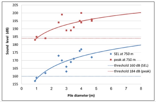
Figure 52. Noise level (SEL and peak) during offshore constructions as a function of pile diameter (Koschinski, 2011)
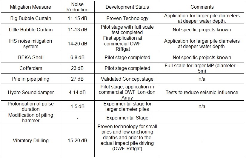
The most notable mitigation measures in use or development, related to offshore piling, and their noise mitigation potentials are tabulated in the table below (Koschinski, 2011):
Table 22. Mitigation measures in use or development and their noise mitigation potentials
Some of the above mentioned technologies relevant to XL monopiles installation are displayed in the pictures bellow.
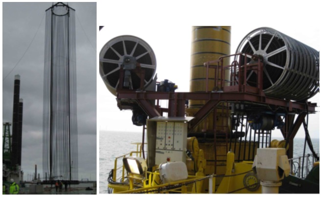
Figure 53. Little bubble curtain of vertical hoses (Koschinski, 2011)
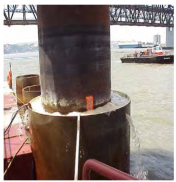
Figure 54. Isolation casing with additional bubble curtain (Koschinski, 2011)
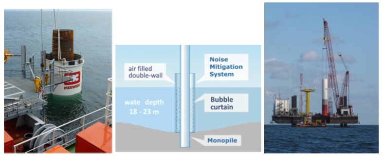
Figure 55. IHS system (Koschinski, 2011)
Seabed habitat disturbance
Moving on to impacts that do not concern XL monopiles specifically, but offshore wind farms in general, the loss of or disturbance of the seabed habitat can be addressed. This is a result of many factors.
The main factor is scour protection. One of the important characteristics of offshore foundations is the instability of the seabed. Bearing in mind this aspect, four types of soil instabilities may be considered:
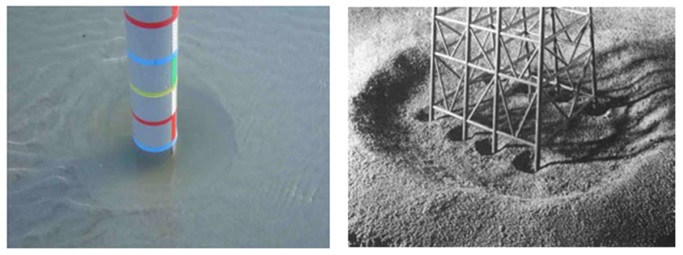
Figure 56. Scour phenomenon (Tempel Van Der, et al.)
Whilst the substructure for the wind turbine is in place, the hydrodynamic field increases locally, what means greater sediment transport and erosion process. The local physical impact of this process will then increase the scouring of the seabed that surrounds it. The water flow mixes the sand particles and transports them away from the structure, which as a result leave a hole in the surface around the structure. Scour creates depressions that are shallow and wide, with the possibility of a cavity occurring around the structure. The likelihood of scour protection being required for XL monopiles is high. (Nielsen et al., 2013) The depth of untreated scour is usually 1.38 times that of the monopile diameter. In spite of research that has been carried out, especially within oil and gas industry, there is still a high degree of uncertainly of the potential depth of scour protection needed. (Whitehouse et al., 2011)
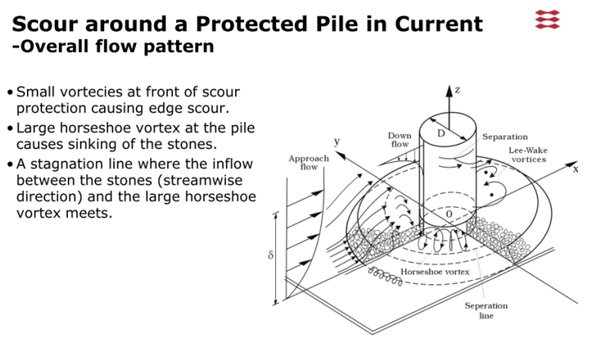
Figure 57. Scour around a pile (DTU Mechanical Engineering, Technical University of Denmark)
Although there are some measures that can be used to estimate scour, the better understanding of this process may help designers in selection of a more tailored design for any given location. The likelihood that the scour will occur around an offshore turbine has to be taken into account in the design process.
Scour has an effect on three main parameters (Van Der Tempel, J. et al):
When scour is likely to happen, there are two aspects that may influence the resistance of the surrounding soil. Firstly, the upper layers of the soil are removed, hence the resistance of the soil decreases. Secondly, the upper layers contribution to the overburdened pressure is removed and reduces the limit of the resistance that is present in the lower layers. Bearing this in mind the majority of the offshore oil and gas structures is supported on jackets. This is due to the fact that in jackets the main loads are axial not lateral forces, hence a scour hole does not have any significant impact on the foundation behaviour. Offshore wind turbines are usually supported on monopiles that transfer lateral loads. Therefore, in case that the top of the soil is removed due to the scour phenomenon, monopiles need greater embedment to ensure sufficient lateral bearings. The worst design scenario must be considered during the design process i.e. the maximum scour depth with the maximum loads. Another aspect of the design of offshore wind turbines is the natural frequency of the supporting structure. The structure needs to be tuned to its frequency window in order to avoid resonance phenomenon. If scour occurs, it has an overall impact on the dynamics of the structure and lower its fist natural frequency, what may lead to resonance or extensive displacements of the structure.
The power cables that are connected to the turbine are usually supported on the seabed by the plastic J-tubes. Hence, when scouring occurs, the J-tube spans over the scour hole what may damage cables. Thus, scour phenomenon must be considered during the design process of J-tubes.
There are many forms of scour protection such as asphalt, concrete mattresses, composite, collar and rubber mats. However, most of them require a lot of offshore works. The most cost effective methods that is dumping of crushed rock. In some cases several layers of rock are needed to prevent the smaller particles from being washed away from between the larger rocks. (Van Der Tempel, J. et al) Figure below, shows a typical design of scour protection. In this case 6500 tonnes of rock have been used. Rocks effectively fix the seabed, making the design of the foundation depth, the natural frequency and the J-tube issues much easier.
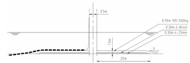
Figure 58. Usage of layers of rock as scour protection (Van Der Tempel, J. et al)
Apart from scour protection that is needed for cables as described above, cable installation is also a procedure that affects seabed and the local sediments. All the cabling equipment is buried at around 2-3m depth. The scale of this effect varies and depends on the sediments grain size, hydrodynamics, turbidity and the magnitude of the species and habitats sensitivity living at the site.
Finally, there is a risk of heating of the sediments around the cables. Studies undertaken in the Nysted offshore wind farm indicated that the highest temperatures that have been recorded ranged from –0.2ºC at the sea bed, 0.3ºC at 10cm below the sea bed, 1.4ºC at 20cm below the seabed to 2.5 ºC at 50cm below the seabed. Measurements taken at 30cm distance from the cable ranged from –0.1 ºC at the seabed, 0.2 ºC at 10cm below the seabed, 0.5ºC at 20cm below the sea bed to 1.3ºC at 50cm below the sea bed. The majority of animals inhabit the top 5-10cm in the open waters and the top 15cm in intertidal areas where the observed temperature increases are at their lowest, although some organisms may burrow deeper. (Eleftheriou and McIntyre, 2005)
On the other hand, there may be some positive impacts on seabed due to some alteration to it. This could result in a new habitat for microorganisms to settle on, creating artificial reef structures.
Concluding, there are lots of studies tackling the effects of the offshore wind farms on seabed morphology and microorganisms. The majority of these studies, though, have been conducted on regular size monopiles. However, further work is needed on XL monopiles, to determine how their foundation size is associated with the impacts described above and come to a conclusion whether they are similar or different to those recorded for monopiles.
Impact on fish
Noise is the main danger for fish and it is associated with many of the marine environment activities. During all the phases of the construction works, the surveys and the vessels movements, noise is being generated. Even though there are lots of studies tackling the impacts of the underwater noise, the results and the predictions about these results differ a lot. However, the available information puts 70dB as an average limit for ambient noise in the marine environment (Assessment of the environmental impact of offshore wind-farms, 2008).
There is a huge legislative framework protecting fish during offshore wind farms construction. Some of the main publications that could provide better guidance of the issues are:
Regarding offshore wind farms, noise impacts should be divided in three different stages. Pile driving, the operational phase and finally, the breakdown phase. During all these stages, noise is generated leading to the disturbance of the marine environment.
According to Assessment of the environmental impact of offshore wind-farms, 2008, the noise associated with the construction of offshore wind-farms could affect marine fish in several ways:
Mitigation measures for the noise impacts could be lots and various. Except the mitigation measures proposed in the “Pilling noise impact” paragraph, other measures such as the reduce of the vessels speed during all the phases of the project as well as them being stationary during the installation period would be one sufficient way to mitigate the problem of the vessels movements produced noise.
Finally, impacts such as the noise during the operation of the wind farm or ones that arise through electro-magnetic fields (EMF) need to be identified and vary depending the construction site and the specific species living at it. In general, though, we could say that neither the noise of the wind farms operation or the EMF are major risks for the underwater sea life. On the contrary, the fact that, in many wind farm areas fishing has been restricted, could be a positive impact, depending though on the way the species living in it behave.
Impacts on marine mammals
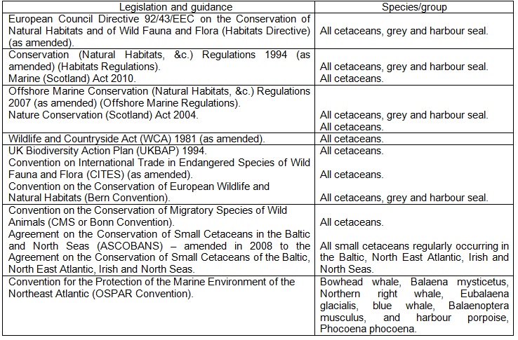
Marine mammals are protected by a range of national and international legislation which makes them one of the most important factors that has to be considered during offshore wind farm project development. According to www.consense.co.uk, 2015, a summary of national and international legislation and guidance relevant to marine mammals is being presented in the table below.
Table 23. Summary of national and international legislation and guidance relevant to marine mammals
The primary impact on marine mammals is, as in the fish case, noise from all the phases of offshore wind farm lifetime with piling noise being the most dangerous. Magnitude of the piling noise can be enough to disturb marine mammals and in some extreme cases can even cause their death. Currently, in German approvals for wind-farms the compliance is required with the threshold of 160dB sound exposure level (SEL) outside a circle with a radius of 750m around the area where ramming takes place. Seasonal restrictions on piling activity may also be relevant (e.g. during calving or pupping season) (Assessment of the environmental impact of offshore wind-farms, 2008).
Such impacts can be mitigated through the application of various methods during all the phases of the project. Some of them are being described in the first paragraph concerning pilling noise as well as the second one concerning the impacts of noise on fish. Minimising the number of vessels used during the construction periods could be another mitigation measure against the vessel engines noise. Finally, the best mitigation measure against the marine mammals impacts is their continuous monitoring during and post-construction i.e. the deployment of a Marine Mammal Observer (MMO).
Impacts on birds
The potential impacts on birds from an offshore wind farm are:
There is a wide number of legislation and guidance that protect birds (www.consense.co.uk, 2015):
In respect with the displacement or the loss of the habitant of some birds it has been observed that, even if the area of the seabed captured by the wind turbines is small, the total area of the whole wind farm is quite big and some bird species may be disturbed by its presence and displace from this specific area (barrier effect).
The other important issue is the collision with a wind turbine structure. In case of the usage of XL monopiles to support higher capacity wind turbine, the structure of OWT is also larger and collision more likely. This risk can be assessed by tools like the one SNH has created (i.e. http://www.snh.gov.uk/docs/C234672.xls) that could estimate it for specific site and species data. It is also necessary to consider the potential danger of the turbulence behind the turbine or the fact that birds migrating at higher levels are forced to fly at levels equivalent to the wind turbines due to circumstances such as the bad weather, etc.
The main mitigation measure of the impacts described above is the constant observation of birds before and after the finish of the project. Radars may be used to analyse how populations or migratory flocks use a site or move around it. This kind of observations are highly problematic, because the behaviour of the species is a rather random and stochastic factor. The studies behind the observation and the flocks behaviour are continuously being undertaken. In the next years the data will be gathered which will help to understand and avoid such impacts.
Seascape/public perception impacts
There are lots of reasons behind public reaction against the wind farms. The problem is larger for onshore wind farms but it also exists for offshore wind farms. In our case, because of the fact XL monopiles are meant to be used for deeper waters and in larger distances from the shore, the problem is being minimized. Anyhow, the visual impact of the wind farms is an important issue and the best mitigation measure against it is to be debated in an open and transparent way with the local populations that are being concerned (sometimes even more widely).
Lots of publications try to focus on this issue, such as Wind Energy and the Historic Environment by Scottish Natural Heritage (SNH), Siting and Designing wind farms in the landscape by Scottish Natural Heritage (SNH) as well and the “Guidelines for Landscape and Visual Impact Assessment