
Boiler Technology
Adapted to small scale heating
Introduction
Boilers are used to turn the energy
originating from a combustion process to usable heat and/or power. If
electrical power is required, the boiler will produce steam (or an organic
vapour if the working fluid is not water) which will undergo a thermodynamic
cycle and power a turbine coupled to a generator. If only heat is required,
steam (organic vapour) generation is not necessary and hot water production
will be sufficient. This is the case when it comes to small-scale heating.
Therefore, only hot water boilers will be dealt with here.
Two main boiler technologies are currently available on the market:
watertube and firetube boilers. In watertube boilers, the water is heated
by circulating in tubes around which the hot combustion gases flow.
In firetube boilers, the hot combustion gases flow through tubes immersed
in a tank filled (or partly filled if steam generation is required)
with water.
Very large boilers with high ratings usually involve high water temperatures
and pressures. Given these operating conditions, watertube designs are
more convenient since only the water tubes should be designed to withstand
such high pressures and temperatures. At lower power, firetubes designs
are usually cheaper. If the output of the boiler does not exceed 20
MW and the pressure 20 bars which is the case for this feasibility study,
a firetube boiler is the most adapted technology.
Description of the firetube boiler technology
1. The Furnace
In a firetube boiler, the combustion takes place in the furnace. This
furnace, usually cylindrical, can either be covered with refractory
material like ceramic (dryback furnace) or be in contact with the boiler's
water (wetback furnace) which significantly increases the heat-exchange
surface. The end of the furnace is called the reversal chamber since
the hot gases make a U-turn and are fed into the first tube-pass. At
the end of the reversal chamber, the gas' temperature must be sufficiently
low to avoid excessive thermal stress on the tubes. The reversal chamber
may be equipped with a drain to collect the water condensing on its
sides (the hot combustion gas usually contain a fraction of water vapour).
Even though the furnace and the reversal chamber only represent 10%
of the exchange surface, they account for 40-50% of the heat exchange
(mainly through radiation) given the very high gas temperatures. Some
biomass boilers include two furnaces to make sure that the combustion
is as complete as possible. In this case, a secondary air supply must
be included in the design of the boiler.
2. The Tube Passes
The first tube-pass is entirely immersed in the water and goes from
one end of the boiler to the other. Depending on the boiler's design
there might be a second tube-pass (also fully immersed) in which case
the boiler is called a "three pass" model (since the furnace is counted
as the first pass). The diameter of the tubes has an important impact
on the heat recovery performance. Clearly, for the same overall cross-section,
a number of narrow tubes will be more efficient than one large tube
since the heat exchange surface will be much greater. However, this
multi-tube layout will be more expensive and small tubes are more likely
to be blocked so maintenance costs will also be greater. The heat-exchange
takes place mainly through a convective process with a limiting heat
resistance on the dry side of the tubes.
3. Combustion Gas Circulation
Firetube boilers represent a significant resistance to gas flow: the
combustion gas circulation is made possible by the use of a fan. Typically,
pressure losses are low in the furnace given its large cross section
but are significant in the reversal chambers (the gas undergoes a U-turn)
and in the tube passes (large gas velocity). The so-called "draught
loss" must be calculated (many correlations are available in the literature)
and the fan power deduced.
4. The Water Tank
Contrary to firetube boilers designed for steam generation where a
steam disengagement surface must be provided, the water tank of hot
water firetube boilers is completely filled with water.
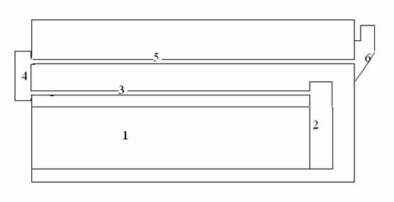
Figure 1: Typical firetube boiler
-
Furnace
- Reversal chamber
- Second tube pass
- Front smoke box
- Third tube pass
- Gas outlet
Additional Equipment
1. Dust Collection Equipment
Dust production in boilers greatly varies with the kind of fuel, the combustion
equipment and the flow pattern in the boiler. If the amount of dust released
exceeds environmental guidelines, dust collection equipment must be added
to the boiler. Different technologies with different efficiencies are
available.
- Cyclones consist of a number of tubes equipped with swirl vanes which give the exhaust gases a swirling trajectory. The induced centrifugal force drives the dust particles towards the periphery of the tube and the dust then falls in the dust hopper. Typical efficiencies are around 85%-95% (mass percentage collection). This appears to be a common technology in small-scale biomass boilers.
- In gas scrubbers, the dust-laden gas is brought into contact with a water spray which traps the dust particles. The water must then be treated or disposed of by appropriate means. The use of gas scrubbers increases the amount of exhaust gases since additional water vapour due to water droplet evaporation will be released. Such systems are often used when the exhaust temperatures are high since water evaporation will cool down the gases. Typically efficiencies range from 95% to 98%.
- Fabric/bag filters can be used to trap the dust before it is rejected in the atmosphere. This kind of technology is only adapted when dealing with relatively low temperature gases (<260°C) since the filters cannot withstand high temperatures. Besides, care must be taken that the filters do not operate at temperatures below the dew point of the various exhaust gases or severe corrosion should be expected and the filters might get blocked. The bags have to be cleaned or shaken regularly to avoid dust build-up. Efficiencies are usually around 99%.
- In electrostatic precipitators, the dust particles are charged by passing through electric wires and are then collected on oppositely-charged plates. Here again, gas dew must be avoided since corrosion would be problematic. This kind of collection equipment is more expensive than the previous technologies but its efficiency is above 99%.
2. Heat Recovery Equipment
The exhaust gases leaving the boiler are often still at high temperature
and can be used to increase the efficiency of the boiler. This is usually
done by means of an economiser or an air heater. The latter, which is
used to pre-heat combustion air, is not currently used in firetube boilers.
However, economisers (which heat the feedwater) are sometimes used. The
use of the feedwater is dictated by its comparatively low temperature
resulting in greater heat exchange for a given surface. Economisers are
constructed from plain or finned tubes made of steel or cast iron. The
extended surface is always orientated towards the gas side since the metal-gas
thermal resistance is the limiting resistance. Care must be taken that
the temperature of the metal (which is very close to that of the feedwater)
does not drop below the dew point of the acids present in the exhaust
gases. This would lead to the build-up of an acid film resulting in corrosion
and fouling.
3. Fouling and Slagging in Biomass Boilers
Apart from the burner technology, the use of biomass has an impact on
fouling and slagging in the boiler. In comparison to conventional fuels
such as coal, the composition of biomass fuels is very variable. However,
generally speaking, the hot combustion gases lead to more difficulties
than in fossil-fuelled boilers. This is mainly due to alkali group metals
such as Na and K. These metals have low melting points and tend to melt
on tube surfaces which increases the ash deposition on the tubes. The
build-up of such deposits increases the thermal resistance of the tubes
and therefore the tube temperature, enabling the melting of other substances.
Besides, this leads to severe corrosion. Fouling and slagging seem to
be worsened by the presence of chlorine which increases the mobility of
inorganic compounds.
Finally, deposits from biomass fuels are denser and more difficult to
remove than in conventional fossil-fuelled technologies. In short, biomass
boilers are more prone to tube-blocking and the maintenance costs will
be higher. This can be minimized by avoiding small tube diameters and
by the addition of some compounds containing sulphur (which seem to reduce
the amount of deposits). In some cases, an automatic cleaning system is
included in the boiler: for example, some Swedish pellet boilers are equipped
with helical screws.
References
Industrial boilers (Gunn, Horton)
Power boiler design, Inspection and repair (Mohammad A. Malek)
Potential applications of renewable energy sources, biomass combustion problems in boiler power systems and combustion related environmental issues (Ayhan Demirbas, Progress in energy and combustion sciences, Elsevier)
Experimental studies of a biomass boiler suitable for small district heating systems (Lundgren,Hermansson, Dahl, Biomass and Energy, Elsevier)
Utilizing biomass and waste for power production - a decade of contributing to the understading, interpretation and analysis of deposits and corrosion products (Flemming Jappe Frandsen, Fuel, Elsevier)