Network solution of air flow
ESP-r supports the calculation of air movement via flow networks which are composed of ,nodes, components and connections
Flow nodes are generally associated with thermal zones and with points on facades where air passes i.e. where they form boundary conditions. We then create and locate flow components e.g. cracks, fans, openings and specify how they are linked to the nodes as in the figure below.
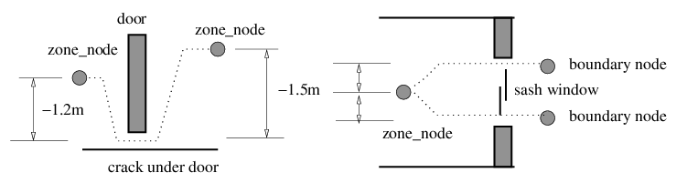
One the left is crack under a door - there are two zone nodes and a crack component. The crack is located relative to each node via a height difference. When the network is solved the crack component will restrict the flow along the path based on its attributes and the pressure difference between the two nodes.
On the right is a sash window which is slightly open. There is a node at the zone and two boundary nodes (each located just outside of the facade at the centre of the openings). There are two parallel flow paths. The openings could be represented by a simple opening or an orifice. Usually a flow control would be associated with each of the paths to adjust the window opening. When the network is solved both buoyancy a pressure are taken into account.
You can find out more about node types here and you can find out more about component types here.
Infiltration
Air flow via linkages between the ambient and zones are counted as INFILTRATION. Both mono and bi-directional flows are supported along a flow connection.
Users wishing to approximate natural ventilation and leaky facades should look here.
Ventilation and mixing
Users wishing to represent stratification should look here.
Users wishing to represent large openings between rooms e.g. between perimeters and core zones should look here.
Users wishing to represent undercuts in doors should here.
Mechanical ventilation
In buildings with mechanical ventilation the most abstract approach is to schedule and control infiltration. A less abstract approach is a flow network with an additional (simple) zone which act as a mixing boxe where ideal controls are used to temper the air. Information gleaned from this can then be used to guide the creation of more detailed approaches.
Air flow controls
In ESP-r control can be applied to flow components e.g. to throttle fans or adjust doors and windows. Control is based on a nominated sensor type and location, control logic, a schedule and a nominated actuator (the flow component). Simple controls are simply enacted and more complex AND OR logic can be implemented. For more information see [TO BE DONE]
Hybrid air flows
In buildings with a mix of scheduled air movement, air movement via system components and naturally driven infiltration the usual approach would be to:
Back to top | Back to Welcome page