
Introduction
 A hydrofoil is a specialized version of the aerofoil that is manufactured to work in water. The word Aerofoil actually refers to the shape of the structure, rather than the structure itself. It uses Bernoulli's principles of fluid mechanics to create an aerodynamic force. This aerodynamic force has two components; the perpendicular component to the direction of motion is called lift (L) and parallel component to motion is called drag (D). The ratio L/D is an important performance characteristic for aerofoils. The higher this ratio is, higher the performance of the aerofoil. Most aerofoils require a positive angle of attack to generate a lift, but cambered aerofoils can generate lift at a zero angle of attack.
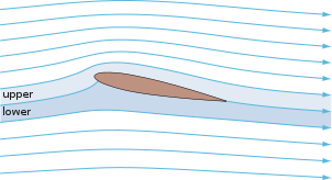
The passing of a fluid in the vicinity of the aerofoil creates different velocity profiles around the aerofoil which results in different pressure distribution, via Bernoulli's Principle. The average velocity of the flow on the upper surface of aerofoils is higher than the average velocity on the lower surface and this creates an upward positive pressure gradient.
There are many applications of aerofoils in industry. An aerofoil wing put at the back of an automobile can improve traction, increase stability and performance. All turbine blades are made in shape of an aerofoil. In aerospace, plane wings and helicopter blades are shaped like aerofoils. Sails are also designed as aerofoils, and underwater parts of boats like the keel use the same principle. In renewable energy devices, from wind turbines to marine current devices, aerofoils have a wide variety of use. Even in organic life, we can see the usage of aerofoils in the wings of birds.
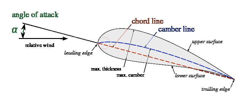
Terminology
Hydrofoil in our Project
The reason that a hydrofoil is considered as a buoyancy device is that it creates dynamic lift as well as buoyancy. The angle, theta, between seabed and mooring line should be as high as possible to decrease footprint and to increase the velocity of flow around the turbine (see Velocity Profile).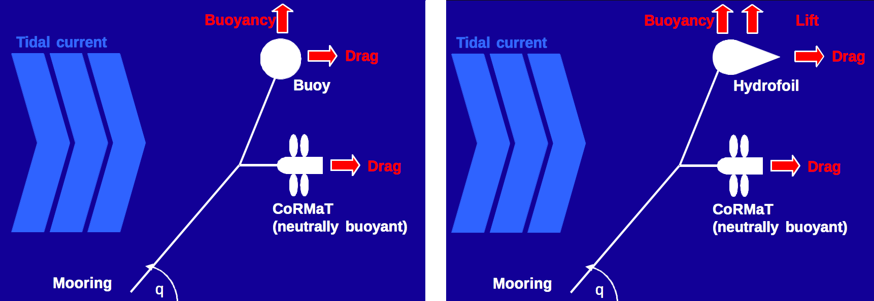
The extra dynamic lift is a very valuable option to achieve these goals. However, an important consideration is what will be the added cost and complexity over added performance? If the gain of performance does not warrant the extra problems that a hydrofoil is going to cause the project, a simple buoy is a more viable option. In order to simplify the calculations, a symmetrical hydrofoil is chosen.
Issues about the hydrofoil