Velocity Profile
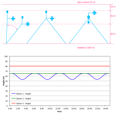
The following explains the difference between each of the 3 mooring options investigated, in terms of their position in the vertical velocity profile, and the resulting flow velocity at the turbine in each case. Assuming a 100m depth, for each of the 3 mooring options, the objective is to maintain both the turbine and the buoy within the 35 m high window, in order to avoid the low energy flow in the bottom 50 m and the wave-induced turbulent zone in the top 15 m.
Mooring Option 1
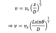
In Option 1 (Shallow Buoy - Single Line), the depth of the turbine and the buoy vary as a function of the flow velocity, since the drag forces increase as the flow velocity increases. Therefore, the height of the turbine varies over both the diurnal and bi-monthly tidal cycles. However, the flow velocity is a function of depth, due to the variation in the vertical velocity profile. Therefore the turbine height and the flow velocity the turbine experiences are inter-dependent, requiring an iterative calculation, derived as follows:
The height of the turbine above the seabed is calculated as follows:

where L is the length of the mooring line and theta is the angle between the seabed and the mooring line.
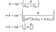
The vertical velocity profile is calculated as follows:
where v is the velocity at height z above the seabed and vs is the velocity at the surface.
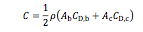
The angle between the seabed and the mooring line is calculated as follows:
where B is the buoyancy force, FD is a drag force, CD is a drag coefficient, the subscript b refers to the buoyancy, the subscript c refers to the CoRMaT turbine and C is a constant defined as follows:
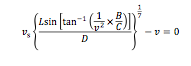
For any given surface velocity, vs the velocity, v at the turbine, located at height, z above the seabed is calculated by an iterative solution of the following:
Mooring Options 2 and 3
In Option 2 (Shallow Buoy - Multiple Lines) and Option 3 (Deep Buoy - Multiple Lines) the turbine height is effectively independent of the flow velocity, due to the additional mooring lines balancing the mooring system. Therefore the height of the turbine is constant over both the diurnal and bi-monthly tidal cycles. These options therefore have the advantage that the turbine height above the seabed can be increased, whilst maintaining the buoy and turbine below the wave-induced turbulent zone in the top 15 m of the profile.