|
Basic principles of operation The fuel cell is an electrochemical system which converts the chemical energy of a conventional fuel, directly into d.c. electrical energy. The basic principle of operation is illustrated in Fig.1. A fuel cell comprises two porous electrodes, with a conducting electrolyte betwen them. At the anode,the hydrogen gives up electrons to the electrode, and enters the electrolyte as a positive ion (H+), while at the cathode, the oxygen takes electrons and enters the electrolyte as a negative ion (O2- or OH-). The respective ions combine in the electrolyte and form water, while the electrons move through the external circuit, to produce electric current. Since these systems do not rely on thermal energy conversion, they are not bounded by Carnot efficiency limitations.
When fuel other than hydrogen is used, fuel processing or reforming is required.
The role of the reformer is to convert any fuel into a hydrogen rich stream of gas. This is
attained by mixing the fuel with steam (typical steam-to-carbon-ratio: 2.5). An additional
role of fuel processing, is to ensure that CO is converted to CO2
(gas shift conversion). Thus, steam temperature has to be high enough to favour the
above chemical reaction. |
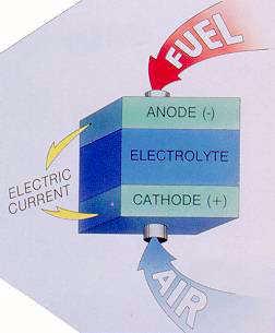 |
| Fig.1: Fuel cell - Principle of operation
|
As mentioned above, FC are not bounded by the thermodynamic laws that limit Carnot cycle
efficiencies. This is due to the fact that chemical energy of a fuel is directly
converted into electricity, without intermediate conversion into heat, as in conventional
power schemes. Hence, theoretical FC efficiencies reach 83 %. However, practical values
(without heat recovery) are about 50 %.
A fuel cell is capable of being switched-on and operate at full power, in 30 ms.
The efficiency is not affected by load variation, as long as it remains above 30 %
of full load.
Because of their simplicity of operation and the absence of moving parts, fuel cells are
very reliable and need only 1/4 of the routine maintenance of conventional systems.
Additional components, such as coolers and blowers are highly reliable, because of their
wide use in industry.
Fuel cells have a projected life of 40,000 h of operation at full load.
The ideal fuel for optimum FC operation is hydrogen, although any two materials that can
undergo an oxidation reaction, can be used as fuels for a FC system.
The following fuels are considered:
The current produced from a fuel cell is proportional to the electrode area, and the
potential output can be increased to meet the necessary power levels, by stacking FC
in piles.
Depending on its size and electrical output, a FC system can be used for a variety of
apps, ranging from micro-scale power genration for modular buildings to large-scale
power generation, possibly as prime povers in co-generation.
The only source of noise is the small blowers, that are used for cooling and supplying
the cell with air.
The SOx and NOx emissions are negligible, while emission of
greenhouse gases is much lower comparing to the conventional power schemes.
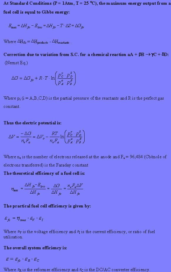
The basic thermodynamic expressions that govern fuel cells are depicted below:
We have designed mathematical models for assessing the energy performance of fuel cell systems,
and incorporated these models on spreadsheets. General information on the
mathematical model
, and details and the spreadsheets for the following types
of fuel cells, are given in our assessment method pages:
Reforming of the fuel to hydrogen is required for the hydrogen to water reaction to occur.
The reforming reaction of methane takes
place at temperatures circa 800C and absorbs some of the heat which results from the fuel
cell reaction. Internal reforming may be used within the high temperature fuel cells. With
low temperature fuel cells the temperature within the fuel cell is insufficient for the
reforming reaction. Also, impurities such as CO or sulphur will poison the platinum catalysts
so external reforming of the fuel to pure hydrogen is required for these types.
The main characteristics of the different types of fuel cells are described below.
PAFC (Phosphoric Acid Fuel Cells)
PAFCs have an operating temperature of 200 �C and a practical FC efficiency, epr ,
of 40%. It is the FC that has mostly been exploited, mainly due to its
high grade heat, which can be used in small-scale CHP. The power output varies from 200 kW
to 20 MW. The main disadvantage is that it has no self-starting capability, because at
lower temperatures (40-50 �C) freezing of concentrated Phosphoric Acid occurs. In order to
reduce losses, the cathode catalyst and the reformer need to be improved.
AFC (Alkaline Fuel Cells)
The operating temperature of AFCs is ~70 �C and their power ouptut is 10-100 kW. They have
been widely used for space and defense applications, where pure hydrogen is used. Their
excessive cost and sensitivity to CO2 , have restricted their research and
development, no matter their high efficiency and power density.
PEM (Proton Exchange Membrane)
PEMs or SPEFC (Solid Polymer Electrolyte Fuel Cells) were the first ones to find practical
application.
Having an operation temperature of 80 �C, a practical efficiency, epr , of
50%, and power output in the range of 5-200 kW, they are ideal for transortation and
portable power. Additional advantages are their high response, the small size and low cost.
An attractive future development is the Direct Methanol Fuel Cell (DMFC). This uses methanol as
the fuel without the necessity for a reformer. Further development of the platinum group
compound catalysts is required before a sufficient power density will be obtained for the
cost of the precious metals.
MCFC (Molten Carbonate Fuel Cells)
MCFC is a very attractive technology, basically due to the simple overall plant design and
because they don't need external reformers. Their high temperature of operation (600 �C)
suggests their use in cogeneration. They have high practical efficiency (50%) and their
power output may range from 500 kW to 60 MW. However, the significant corrosion problems of
the electrodes and the catalyst have lagged their application.
SOFC (Solid Oxide Fuel Cells)
SOFCs have an operating temperature of 1000 �C and practical efficiency, epr ,
of 45%.
It is a very promising technology, because they don't need external reforming, they have
high fuel flexibility and high quality waste heat. One basic problem concerns the materials
used. Although ceramics are quite cheap, they are difficult to fabricate in forms and
shapes that can accommodate the high thermal stresses.
The model can easily be extended for other fuels and other types
of FCs, although, in the case of MCFC, the fuel cell reactions
should be considered carefully.
This assessment method can give even more accurate results, it the
specifications of the heat exchangers, the control equipment and
the dc/ac power converters are known.
For further details of the availability of the different fuel cell types and the leading
suppliers see our technical review on the
current and future commercial availability of fuel cells.
Fuel Cell Type
Polymer
Electrolyte
Membrane Phosphoric
AcidCarbonate
Solid
Oxide
Electrolyte
Ion Exchange
Membrane Phosphoric
AcidAlkali Carbonates
Mixture Yttria Stabilized
Zirconia
Operating Temp., °C
80
200
650
1,000
Charge Carrier
H+
H+
CO3=
O=
Electrolyte State
Solid
Immobilized
LiquidImmobilized
Liquid Solid
Cell Hardware
Carbon- or
Metal-Based Graphite-
BasedStainless
Steel Ceramic
Catalyst
Platinum
Platinum
Nickel
Perovskites
Cogeneration Heat
None
Low Quality
High
High
Fuel Cell Efficiency, %LHV
<40
40-45
50-60
50-60
Fuel cell types Courtesy US Department of Energy
