Flettner Rotor Theory
The principal that the Flettner Rotor uses is called the Magnus effect. This phenomenon can be seen in more mundane applications such as the curving of a ball in many ball sports. The basis of this effect can be understood by considering the boundary layer of a fluid flowing over a body. If we use the example of a tennis ball: as it is rotating and the flow passes over it, one side will force air to slow as it moves against the motion of the air, similarly one side will force the air to speed up as it moves in the same direction. From Bernoulli’s theorem we know that a fluid’s pressure increases as its speed decreases. Hence, the spinning of a ball as it moves through a fluid creates a pressure difference from one side to another. This pressure difference results in the ball being forced to move towards the side of low pressure, causing a swerve on the movement of the ball.
(ENERCON, 2013)
The Flettner rotor utilises this magnus effect in the form of a mechanical rotor sail. Instead of a ball, the Flettner rotor is in a cylindrical shape. When positioned in a cross wind the spinning of the cylinder by an internal motor creates a pressure difference between the bow and stern side of the cylinder, providing a forward thrust force on the boat forward. The concept is demonstrated in the following video created by NorsePower Ltd. (a company that manufactures Flettner rotors).
Force diagram of Flettner rotor (Lele & Rao, 2017)
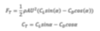
The figure above shows how the lift and drag forces combine to produce a useable thrust. The rotor can be spun clockwise or anticlockwise, but the forward thrust depends heavily on the angle of attack of the apparent wind. This forward thrust can be calculated with the equation below:
Where F_T is the forward thrust force, L and D are the lift and drag forces respectively, and α is the angle of attack of the apparent wind.
Lift and drag is often presented in terms of the lift and drag coefficients, which act as a dimensionless value to determine the amount of lift available from a rotor independent of its size, allowing easier comparison between studies. They can be expressed as the following equations:
Where Cl and Cd are coefficients of lift and drag respectively, ρ is the density of air, U is the apparent wind speed (made from components of the true wind speed and the ship speed), and A is the projected area of the cylinder (in this case height x diameter).
Substituting lift and drag equations into the forward thrust equation, we can simplify to obtain what will now be referred to as thrust coefficient, C_T.
The operation of a Flettner Rotor is very much dependant on the conditions it operates in. A slow ship speed allows an angle of attack closer to 90° as is suggested in the above diagram, and hence improved forward thrust. The route a ship takes must also be carefully optimised to achieve the largest power savings possible. The coefficients of lift and drag can be optimised, however, with a number of design considerations.
Spin Ratio
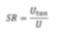
The ratio between the apparent velocity of the air and the tangential velocity of the cylinder surface, known as the velocity ratio, or spin ratio, is denoted SR.
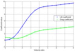
The spin ratio had a sizeable effect on the Strouhal number of the wake flow, a dimensionless number relating to the unsteadiness of fluid flow and the associated oscillatory motion (Badalementi & Prince, 2008). Smaller spin ratios for FRs result in long eddy formations (a low Strouhal number) downwind of the rotor, while inversely, larger spin ratios will cause much shorter eddy formations (and a larger Strouhal number). Disregarding complicated fluid dynamics concepts, the spin ratio is one of the key controllable parameters that dictates the performance of the Flettner Rotor. As shown below, the lift and drag are clearly dependant on the spin ratio of the rotor, and must be optimised for the wind conditions.
Relationship of SR and Cl/Cd for a low Reynolds number study (Pearson, 2014)
Aspect Ratio
The aspect ratio of the FR describes the ratio between its height and diameter. Not only does this ratio effect the stability of the vessel, but also the performance of the FR. Smaller aspect ratios (short and wide cylinders) have proven to provide less lift, where theoretical studies have shown extreme lift is available at greater aspect ratios, although there is some disagreement between studies on these effects. A comprehensive review of research into Flettner Rotors shows that higher aspect ratios can yield higher lift and lower drag coefficients, but this ultimately depends on other design variations such as the size of the Thom disc (Marco, et al., 2016).
Thom Disc
Flettner Rotors today use an end plate, also known as a Thom disc, to optimise the aerodynamic efficiency of the rotor at the tip. Although studies into this modification of the FR show it to dramatically improve the lift produced by the FR, its effectiveness varies with the other parameters described in this section. In any case, it is seen as a positive addition to the FR. It’s size, often described as a ratio between the plates diameter and the cylinders diameter must be optimised for a given aspect ratio and spin ratio of the FR.
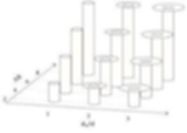
Changing aspect ratio and Thom disc size can be observed on this chart, which has aspect ratio increasing with each row, and Thom disc size increasing from left to right:
(Devaraj & Raju, 2017)
References
Badalementi, C. & Prince, S. A., 2008. Vortex Shedding from a rotating Circular Cylinder at Moderate Sub-Critical Reynolds Numbers and High Velocity Ratio. London, ICAS.
ENERCON, 2013. A Wind-Hybrid Commercial Cargo Ship. Hamburg, ENERCON.
Lele, A. & Rao, K. V. S., 2017. Net Power Generated by Flettner Rotor for Different Values of Wind Speed and Ship Speed. s.l., IEEE.
Marco, A. D. et al., 2016. Flettner Rotor Concept for Marine Applications: A Systematic Study. International Journal of Rotating Machinery, Volume 2016, p. 12.
Pearson, D., 2014. The use of Flettner rotors in efficient ship design. London, EEDI.