Energy Supply and Demand Calculations
Navigation
- Introduction
- Manual Calculations
- Computer Based Calculations
- Cost Analysis
The fundamental problem in heating system design is that of estimating the loads on the various subsystems. The more certain the designer can be about the accuracy of these basic load estimates the more meaningful will be his decision about load profiling and his estimates of efficiency during the various load conditions that will arise throughout the heating season.
In most schemes the space heating requirements constitute the most important part of the load. During the last decade or so, there has been rapid development in heating load calculation methods. Some of these are inherently computer oriented while others are designed for manual calculations with some computer support.
Accordingly we have done both manual calculations using the steady state approach and computer based calculations.
Space Heating
It is assumed that a steady state exists between inside and outside temperatures although such
a condition rarely occurs. In the past, air temperature difference has been the sole criterion. The method of calculation recommended by
CIBSE section A5 & A9 is in terms of dry resultant temperature within the space to be heated
and this takes account the mean radiant temperature and this was adopted in our calculation.
Each room of a building is taken in turn and an estimate is made of the amount of heat necessary
to maintain a given steady temperature within the space, assuming a steady lower temperature
outside. The calculation falls into two parts: one relating to conduction through the various
surrounding structural surfaces, walls, floor and ceiling; the other relating to the heat necessary
to warm to room temperature any outside air which, by accident or design, has infiltrated
the space.
The conduction element is calculable from known properties of the building materials, but the
infiltration element poses problemsas the air change rate is not easy to assess
other than by experience.
With so many assumptions and 'rule of thumb' estimates, heat loss
calculations might be considered little better than guesswork. In practice, however, they have
proved
to be a reliable basis for an overall assessment, partly due to the fact that all areas in the
building are treated in a like manner and are thus consistent in response. In addition, the
building structure is itself a moderator, as a result of its thermal inertia, which remains
a significant factor, even in a lightly constructed building which still has floor slabs,
partitions, furniture etc. to absorb and emit heat and thus smooth out any violent fluctuations.
Domestic Hot water Heating
A decision as to the volume of hot water storage and the capacity of the associated heat pump
depends upon some considerations, these are quite different from those that apply to a heating
system. A hot water system, except in the case of industrial processes with a finite time cycle,
has to fill on demand. This depends on a user pattern and can only be approximately projected.
For any particular type of demand, a natural relationship exists between the volume of hot water
stored and the heat pump power required to heat it. In general terms, the more generous the
storage the smaller the boiler capacity needed since it will have a long time to restore the
temperature following draw off.
In many cases, a storage capacity equal to the maximum draw-off in any one hour at peak
conditions will be an adequate provision. The associated heat pump power may then be sized
on the basis that this volume of water will be heated from cold over some longer period such as
two or three hours. A rule of thumb basis of this sort is however acceptable only in
circumstances where no general statistical data is available.

The above approximate method overstates the requirement and more recent fieldwork has proposed
the alternative approach included in the CIBSE Guide, section B4. Here, a series of figures
represents the relationship between storage capacity and plant power for a number of building
types. The values given do not include any allowance for the loss of effective storage capacity
due to cold mixing and hence, an addition of 25 % should be made to the total of the volume
calculated.

MANUAL CALCULATIONS
Approach
The heat load calculation approach is shown in the figure below. The system has been divided into two;
Commercial Complex and Residential Complex. This has been further subdivided into space heating
and domestic water supply as shown in the figure below.
Space Heating
A Typical office has been modelled with a total area of 72m2 per office. The walls are of brick
construction with 50mm polyurethane foam insulation with a total 'U' value of 0.5. The windows are of double glazed construction with a U value of 2.3. Floors are with wooden board with aluminium foil with a 'U' value of 0.70. The roof has an overall 'U' value of 0.643.
Design outside air temperature is considered as -4 oC as per CIBSE for the Glasgow area. The
inside temperature is taken as 20 oC for the office buildings. The height of the room is taken as 3m.
| Sl.No: | Item | Area ( m2) | Temp.Difference (oC) | ' U ' | Heat Load ( watts ) |
| 1 | Walls | 49.5 | 24 | 0.5 | 594.00 |
| 2 | Windows | 12 | 24 | 2.3 | 662.40 |
| 3 | Int. Partition | 36 | 4 | 1.62 | 233.28 |
| 4 | Floors | 72 | 24 | 0.70 | 1209.6 |
| 5 | Roof | 72 | 4 | 0.64 | 184.32 |
| Total | | 241.5 | | | 2883.60 |
q ai - qei = 2883.60/ (4.8x 241.5) = 2.48 0C
q ai = design internal air temperature
q ai = 20 + 2.48 = 22.48 0C
qei = design inside environmental temperature
Air Infiltration rate = 1 per hour
Ventillation allowance= 0.33 w/ m3 0 C
Ventillation Load = 0.33 * V * (q ai - (-4) ) = 0.33 * (72*3) * ( 22.48+4)
= 1887.49 watts
Total Heat Load for one office = 2883.60 + 1887.49
= 4771 watts
Total heat load for the complex ( 15 offices ) = 15 * 4771 = 71500 watts
Domestic Hot Water System
Assuming that there are 120 staff and 75 meals per day are served in the canteen.
For a 3 hour recovery period, the graphs in section B-4 of the CIBSE guide for offices suggest:
For service,
Plant power/ person = .033
Storage required/ person = 1.6 litres
Plant capacity for service = .033 x 120 x(55-10)/(65-10) = 3.24 KW
Storage required = 1.6 x 120x1.25 = 240 litres
For catering,
Plant power/person = 0.065
Storage/person = 3.1 litres
plant capacity for catering = .065x 75x (55-10/65-10) = 3.98 KW
storage required for catering = 3.1 x 75x1.25 = 290 liters
Total Heat Pump capacity required = 3.24 + 3.98 + losses
= 7.22 +losses = 10 KW
Total Storage capacity required = 240 + 290 = 530 litres

Software Overview
Renewable energy technology (RET) projects are not routinely considered by planners and
decision-makers at the critically important stage of initial planning. The RET Screen® Renewable
Energy Project Analysis Software has been developed to help this barrier.
GHG analysis Cost Analysis Financial Summary
RET Screen International is a renewable energy awareness, decision-support and capacity
building tool developed by the CANMET Energy Diversification Research Laboratory (CEDRL)
with the contribution of over 89 experts from industry, government and academia.
The core of the tool consists of a standardised and integrated renewable energy project analysis software that can be used world-wide to evaluate the energy production, life-cycle costs and greenhouse gas emission reductions for various types of renewable energy technologies (RET ). Each RET Screen renewable energy technology model (e.g. Ground Source Heat Pumps etc.) is developed within an individual Microsoft® Excel spreadsheet "Workbook" file. The Workbook file is in-turn composed of a series of worksheets. These worksheets have a common look and follow a standard approach for all RET Screen models. In addition to the software, the tool includes: product, weather and cost databases; an online manual; a Web site; project case studies; and a training course.
Ground Source Heat Pump Model
The RET Screen® International Ground-Source Heat Pump Project Model (Version 2000) can be used
world-wide to easily evaluate the energy production (or savings), life-cycle costs and
greenhouse gas emissions reduction for the heating and/or cooling of residential, commercial,
institutional and industrial buildings. The model can be used to evaluate both retrofit and new
construction projects using either ground-coupled (horizontal and vertical closed-loop) or
groundwater heat pumps.
The main features of version 2000 are:
1) Updated Energy Model and Heating & Cooling Load Calculation worksheets that incorporate calculations based on manufacturer specific data for various heat pumps, as well as improvements to the heating and cooling load calculator.
2) An upgraded Cost Analysis worksheet that allows the user to switch currencies, enter custom cost items, build a custom cost database and consider periodic costs.
3) A new Greenhouse Gas (GHG) Emission Reduction Analysis worksheet, developed with UNEP, that allows users to calculate the estimated GHG emissions avoided .
4) An enhanced Financial Summary worksheet that allows for the analysis of income taxes, greenhouse gas reduction credits and a number of other parameters;
5) New blank worksheets that allow the user to prepare a customised RET Screen project analysis or to develop a companion model to RET Screen.
Version 2000 also includes a number of other new features such as: product, cost and weather databases (ground station data and NASA satellite-derived surface meteorology and solar energy data, including mean earth temperature data across the globe); an online manual; and a training course.
Data Input
The user enters the heating design temperature, which represents the minimum temperature that has been measured for a frequency level of at least 1% over the year, for a specific area [ASHRAE, 1997]. The design temperature is used to determine the heating energy demand.
The heating design temperature values found in the RET Screen online weather database were calculated based on hourly data for 12 months of the year. The user may want to overwrite this value depending on local conditions and "conservative" design philosophy.
The user enters the mean earth temperature (şC). This value is used to calculate the ground
temperature at the depth corresponding to the type of ground heat exchanger selected or to
obtain the groundwater temperature. For depths greater than 15 m, the temperature (ground
or water) is assumed to be equal to the mean earth temperature. The RET Screen Online Weather
Database does not provide this value for ground stations. However the NASA satellite database (accessed via the RET Screen online weather database) does provide this value around the globe.
The user selects the type of building intended for the GSHP system. There are three options
available from the drop-down list: "Residential," "Commercial" and "Industrial." The selection
will affect the way in which the model evaluates the building loads and energy demand.
Selecting "Residential" building type will reduce the number of inputs required by the user.
Commercial and industrial buildings have specific features requiring other considerations than
those used for residential buildings. Commercial and industrial buildings typically have much
higher internal heat gains, higher gains from occupants, potentially higher solar gains and
often more complex occupancy schedules. Given all the potential influences upon
commercial/industrial building energy use, prediction of loads and energy demand is a
very site-specific endeavour. The methodology selected for evaluating a buildings load and
energy use is based on the modified bin method [ASHRAE, 1985] where all heat loads and gains
are modelled using a linear relationship with ambient temperature.
The user selects the type of information available to characterise the thermal behaviour of
the building where the GSHP system is to be installed. There are two options available:
"Descriptive data" and "Energy use data." When "Energy use data" is selected, the same
input is required regardless of the building type selected by the user.
Descriptive data: When the user selects this option, physical characteristics of the
building are required for the model to calculate heating and cooling loads and energy
consumption.
Energy use data: When this option is selected, the building design heating and cooling
load as well as the annual heating and cooling energy consumption are entered by the user.
The "Energy use data" option does not offer the same level of flexibility as the "Descriptive
data" option; for example it cannot distinguish between occupied and unoccupied periods in a
building.
The user enters the total floor area (m˛) of the building that is heated and/or cooled,
excluding the basement area. This value is the primary variable used in the model to calculate
the load and energy consumption of the building. The user enters the number of floors for the building, excluding the basement. This value is used in the model to calculate the heat load/gain from the ceiling of the building.
The user selects the type of window area. The options from the drop-down list are: "Standard," "Above average" and "High." From this selection the model determines the total window area as a fraction of the total floor area. The type of windows considered in the model, for all cases, are clear insulated double glazed windows with a shading coefficient of 0.81 and a heat transfer coefficient of 3 W/(m˛·°C) [ASHRAE, 1985].
The user selects the type of insulation level. The options from the drop-down list are: "Low," "Medium" and "High." From this selection the model determines the heat transfer coefficient for the walls and roof of the building, for all building types. Additionally, this selection determines the air infiltration rate and basement insulation level for residential buildings.
The user selects the type of soil that is found at the proposed site. The soil type has a large influence on the size of the GHX. For example, a light dry soil will require a much longer horizontal GHX than a heavy damp soil would. This is due to the poorer heat transfer characteristics and the lower density of the lighter and dryer soil.
The model calculates the typical land area (m˛) required for the selected GSHP system type. This land area is compared to the available land area entered by the user; if the available land area is less than the typical land area required, a "Insufficient land area" warning message in red characters will appear next to this value. If this warning message appears, the user can change the GHX system type or layout to fit the available land area.
The typical land area required for a groundwater system is based on a 6 m radius per well and includes the presence of injection wells. The typical land area for a vertical closed-loop system is based on an average bore hole depth of 91 m.
Typical values for land area range from 50 to 95 m˛/kW for horizontal systems and 1.5 to 12 m˛/kW for vertical systems.
Now, once the user selects the system type the software calculates the area required, length of pipe required etc. also, once the user selects the heat pump characteristics, it calculates the annual energy used and delivered.
Conclusion
In view of the many complexities involved in modelling building thermal performance it is clear that future designs will be based on the more exact method now available using sophisticated computer programs.
The less conventional steady state heat losses are still widely used and provide a useful reference point at the initial stages of design from which the designer can proceed from a well established value of building performance using computer programs.
Conventional steady state heat loss methods also form the basis for the more traditional, often semi-empirical methods of sizing plant and estimating annual energy consumption. This method also forms the basis for many fairly simple programs for use with in house mini computers or programmable calculators
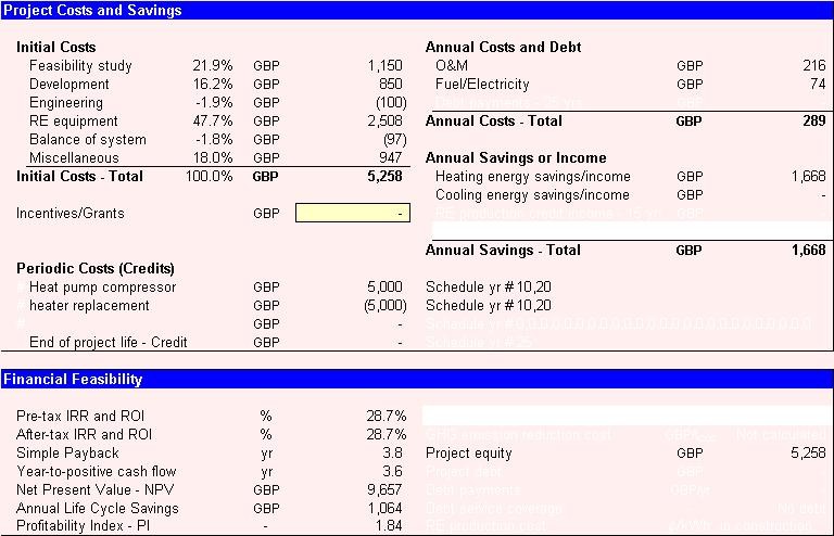
Once a potentially cost-effective ground-source heat pump project has been identified through
the RET Screen pre-feasibility analysis process, a more detailed feasibility analysis study may
be required. This is the case, in particularl, for larger projects, typically larger than 100 kW.
Feasibility studies typically include such items as site investigations, soil/hydrology
assessment, environmental assessment, a preliminary system design, including loop sizing and
layout, a detailed cost estimate and a final report. Feasibility study project management
and travel costs are also normally incurred. These costs are detailed in the section below.
For small projects, such as small commercial systems, the cost of the feasibility study,
relative to the cost of the ground-source heat pump system, may not be justified. In this
case the project proponent may choose to go directly to the engineering stage.
Once a potential ground-source heat pump project has been established as desireable to implement through the feasibility
study, project development activities may follow. For some
projects, the feasibility study, development and engineering activities may proceed in parallel,
depending on the risk and return acceptable to the project proponent.
The engineering phase includes costs for the GSHP system design, tenders and contracting, and
construction supervision. If the project is awarded on a design/build basis, then all of these
costs would be included in the prices provided by the equipment supplier or contractor responsible
for the project. If the project is awarded by tender, based on specifications prepared by a consultant, then there will be engineering charges from the consultant overseeing the project and perhaps the equipment supplier.
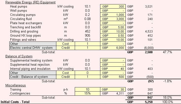
The renewable energy equipment, as defined here, includes, when applicable, the system's heat
pumps, water well pumps, circulating pumps, heat exchanger, anti-freeze solution, drilling,
trenching, GHX pipes, valves and fittings and transportation costs. All cost figures are
installed costs and include overhead and profit. The user may refer to the RET
Screen online product database for supplier contact information in order to obtain prices or
other information required.
The balance of system for a ground-source heat pump project typically includes only a few items
such as the supplemental heating system, the supplemental heat rejection system and the cost
of the building loop piping, valves, fittings and insulation. It is assumed that other cost
components, such as for the required ductwork or transportation costs, are similar to those
for a conventional system and will have a negligible impact on the incremental cost of a GSHP
system.
All of the miscellaneous costs that occur during a project and have not been taken into account
in the previous sections. For GSHP projects these costs can include training and contingencies.
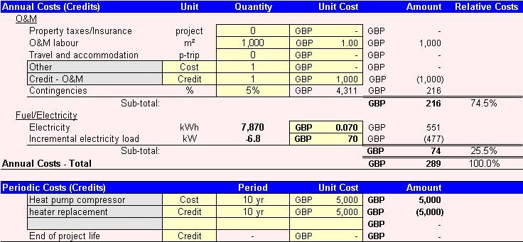
Ground-source heat pump systems usually have a lower maintenance cost than conventional systems. This cost is best expressed in terms of $ per floor area (m˛) and will range from $1.00/m˛ to $3.00/m˛ compared to $2.00/m˛ to $4.00/m˛ for a conventional system.
This item represents the total electrical energy required to run the GSHP system on an annual
basis, both for heating and cooling purposes.
In the case of a small commercial application, there is a potential for a reduction in charges due to off-peak electricity. The model calculates the incremental
peak electricity load, at any point during the cooling or heating season, between the GSHP
system and the conventional heating and cooling system.
A periodic cost represents recurrent costs that must be incurred at regular intervals to
maintain the RET project in working condition. A periodic cost item is entered in the grey
input cell. The user then selects "Cost" from the drop-down list in the unit column. The
interval (in years) over which the periodic cost is incurred is entered in the period column.
The amount of the cost incurred at each interval is entered in the unit cost column.
COST ANALYSIS