MEASUREMENT & CONTROL SYSTEM.vi
General instructions about the LabView programming environment
In order to develop our programme, we chose to work using the programming
environment of the LabView software.
With LabView you build VIs instead of writing programs. You quickly create
front panel
user interfaces, giving you the interactive control of your software system.
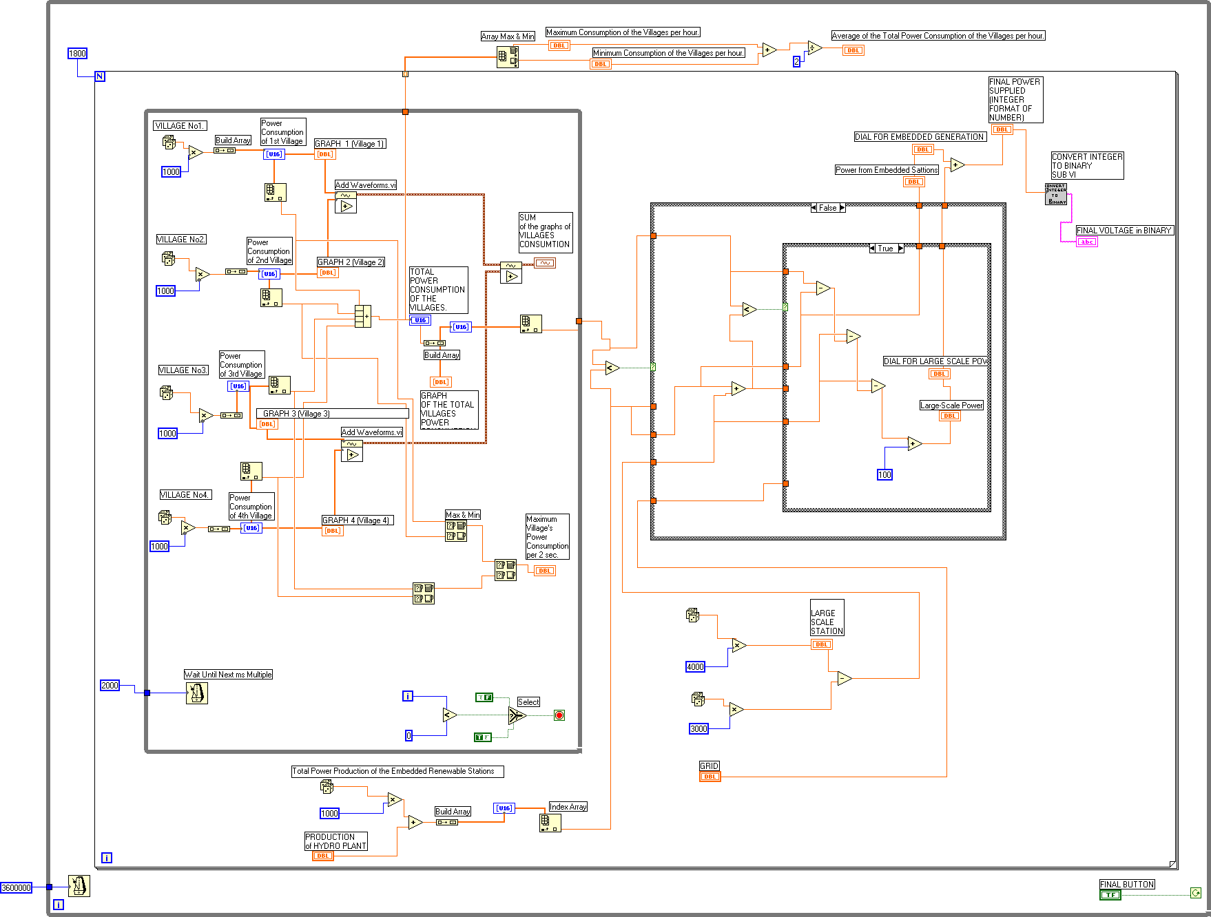
To specify the functionality, you intuitively assemble block
diagrams.
Virtual Instruments (VI'S)
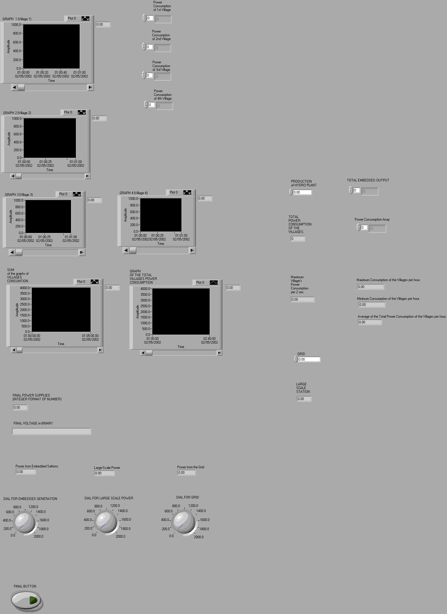
Thus, every VI (Virtual Instrument) is consisted from a front panel where
you put all the instruments that you use, like dials, gauges, meters etc,
and from a front panel where you put all the wires and connections of the
system. You can use the front panel to control your system - while the VI
is running - by clicking a switch, moving a slide, zooming in on a graph,
or entering a value from the keyboard, while the wires of the block diagram
pass the data from one block to the next. Modularity & Hierarchy of VI'S
LabView VIs are modular in design, so any VI can run by itself or be used as part of another VI. You can create an icon for your own VIs, so you can design a hierarchy of VIs and subVIs that you can modify, interchange, and combine with other VIs to meet your changing application needs.
Dataflow Programming
LabView uses a patented dataflow-programming model, called G that frees you from the linear architecture of text-based languages. Because the execution order in LabView is determined by the flow of data between blocks, and not by sequential lines of text, you can create diagrams that have simultaneous operations. LabView is a multitasking and multithreaded system, running multiple execution threads and multiple VIs.
Our programme's main VI and subVI
The main VI of our programme is called "Measurement & Control System.vi".
Further we have created a subVI, which is called "Convert
an Integer to a Binary Number.vi".
The subVI has also an icon (Connector Pane)which is drawn from us and
which is the only thing that is shown to the front panel of the main VI
of the programme.
The connectors of the subVI have defined from us as well.
Analytically, the integer number that we want to convert to a binary number
is the input
connector of the subVI, while the output connector gives the binary number.
If the user of the main VI wants to see the interfaces of the subVI,
he has just to click to
the following icon(Connector Pane for the sub VI )and the front panel
and the block diagram of the subVI will be appeared.
![]()