The channel length,
![]() , as measured from a 1:50 000 scale map, was
found to be approximately 350m.
, as measured from a 1:50 000 scale map, was
found to be approximately 350m.
The maximum water flow rate (i.e. the installed
turbine flow rate),
![]() , can be found from the annual flow
, can be found from the annual flow
curve (fig.2);
![]() . For
the channel material concrete was selected, which has a roughness
. For
the channel material concrete was selected, which has a roughness
coefficient,
![]() , of
, of
![]() . A
desired water velocity,
. A
desired water velocity,
![]() , of 1m/s was chosen,
, of 1m/s was chosen,
arbitrarily, as an initial value (as a standard, for concrete the velocity should be >0.3m/s and <2.0m/s).
Assuming the channel has a trapezoidal cross-section,
the cross-sectional side slope,
![]() ,
,
for concrete is typically
![]() . The
cross-sectional area,
. The
cross-sectional area,
![]() , is given by:
, is given by:

Channel height,
![]() , is given by:
, is given by:
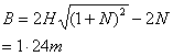
Channel bed width,
![]() , is given by:
, is given by:
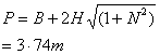
Channel top width,
![]() , is given by:
, is given by:
![]()
For a stable unifrom flow, velocity should
be kept below the critical limit,
![]() ;
;

The following rule should be followed:
![]() .
.
Here,
![]()
So,
![]() .
.
![]() is
suitable.
is
suitable.
The wetted perimeter,
![]() , is given by:
, is given by:
Hydraulic mean radius,
![]() , is given by:
, is given by:
![]()
Now the slope of the channel,
![]() , can be calculated from:
, can be calculated from:

Channel head loss,
![]() , is given by:
, is given by:
![]()
Penstock Losses
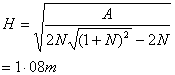
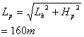
The length of penstock required,
![]() ,can be calculated using simple
trigonometry.
,can be calculated using simple
trigonometry.
The horizontal distance,
![]() , and the height,
, and the height,
![]() , were found from
, were found from
a 1:50 000 scale map.
The penstock length was calulated as follows:
PVC was chosen as the material for the penstock. A suitable internal diameter,
![]() ,
,
for a PVC pipe is
![]() .From tables, the roughness value,
.From tables, the roughness value,
![]() ,
,
associated with PVC was found to be
![]() .Using the values of k, d and Q with
.Using the values of k, d and Q with
reference to a Moody Chart the friction factor,
f, was found;
![]() .
.
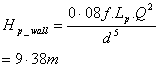
Now, the head loss due to friction on the
pipe wall is given by:
In order to calculate the losses through turbulence in the pipe, the velocity of the water in the
penstock,
![]() , must be calculated:
, must be calculated:

These are different coefficients to calculate turbulence effects for different sections of the penstock.
For example, there are different coefficients for pipe entrance, bends, valves, etc. It is considered
that for the penstock here
coefficients for the entrance and for one valve are sufficient.
The turbulence losses are given by:
![]()
where
![]() is
the entrance turbulence coefficient ;
is
the entrance turbulence coefficient ;
![]() ,
,
and
![]() is
the valve turbulence coefficient;
is
the valve turbulence coefficient;
![]()
so,
![]()
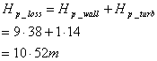
Total penstock head losses amount to: